
Device for sufficiently utilizing hydrogen and oxygen of fuel cell

A technology of fuel cells and fuel cell stacks, which is applied to fuel cell components, fuel cells, fuel cell additives, etc., can solve the problems of large differences in processing, difficulty, and high cost of ejector pumps, and achieve convenient implementation and low price. cheap effect

Active Publication Date: 2007-06-27
SHANGHAI MUNICIPAL ELECTRIC POWER CO +1
View PDF1 Cites 4 Cited by
  • Summary
  • Abstract
  • Description
  • Claims
  • Application Information

AI Technical Summary

Problems solved by technology

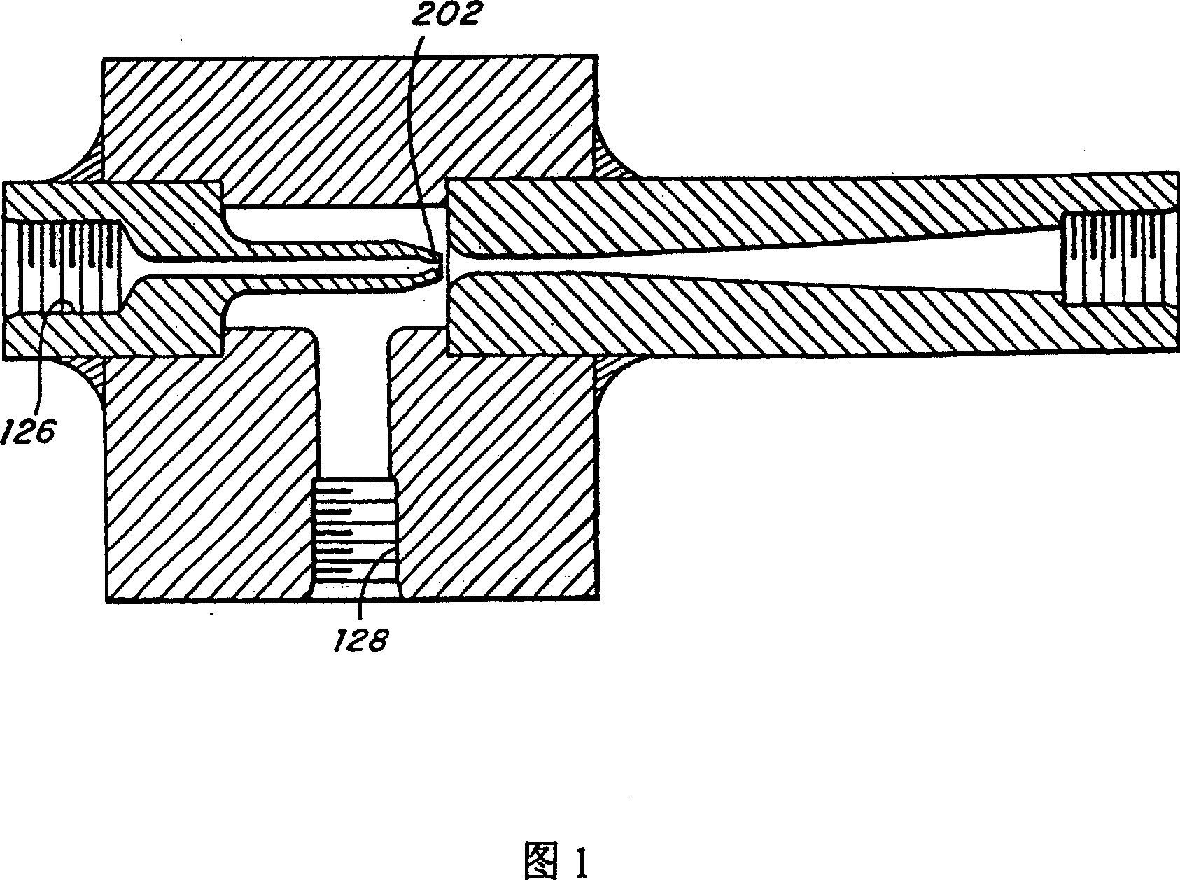
[0020] (1) The processing requirements of ejector pumps are very high and difficult. For different flow requirements, different inlet and outlet pressure requirements and different injection pump volume requirements; the processing differences of ejector pumps are very large and cannot achieve versatility
[0021] (2) The inlet end of the ejector pump often requires a very high pressure of fuel or oxidant, and after passing through the ejector pump, the pressure at the outlet end suddenly drops, resulting in a large pressure difference between the inlet end and the outlet end of the ejector pump
When this pressure regulation control device fails, the pressure at the inlet end of the ejector pump will be equal to the pressure at the outlet end, causing the fuel cell to withstand ultra-high pressure and cause damage
[0022] (3) This automatic pressure adjustment device is mainly composed of a pressure sensor, a solenoid valve, and an electric control valve. It is a very expensive device and can easily lead to loss of control.

Method used


Image

  • Device for sufficiently utilizing hydrogen and oxygen of fuel cell
  • Device for sufficiently utilizing hydrogen and oxygen of fuel cell
  • Device for sufficiently utilizing hydrogen and oxygen of fuel cell

Examples


Embodiment 1

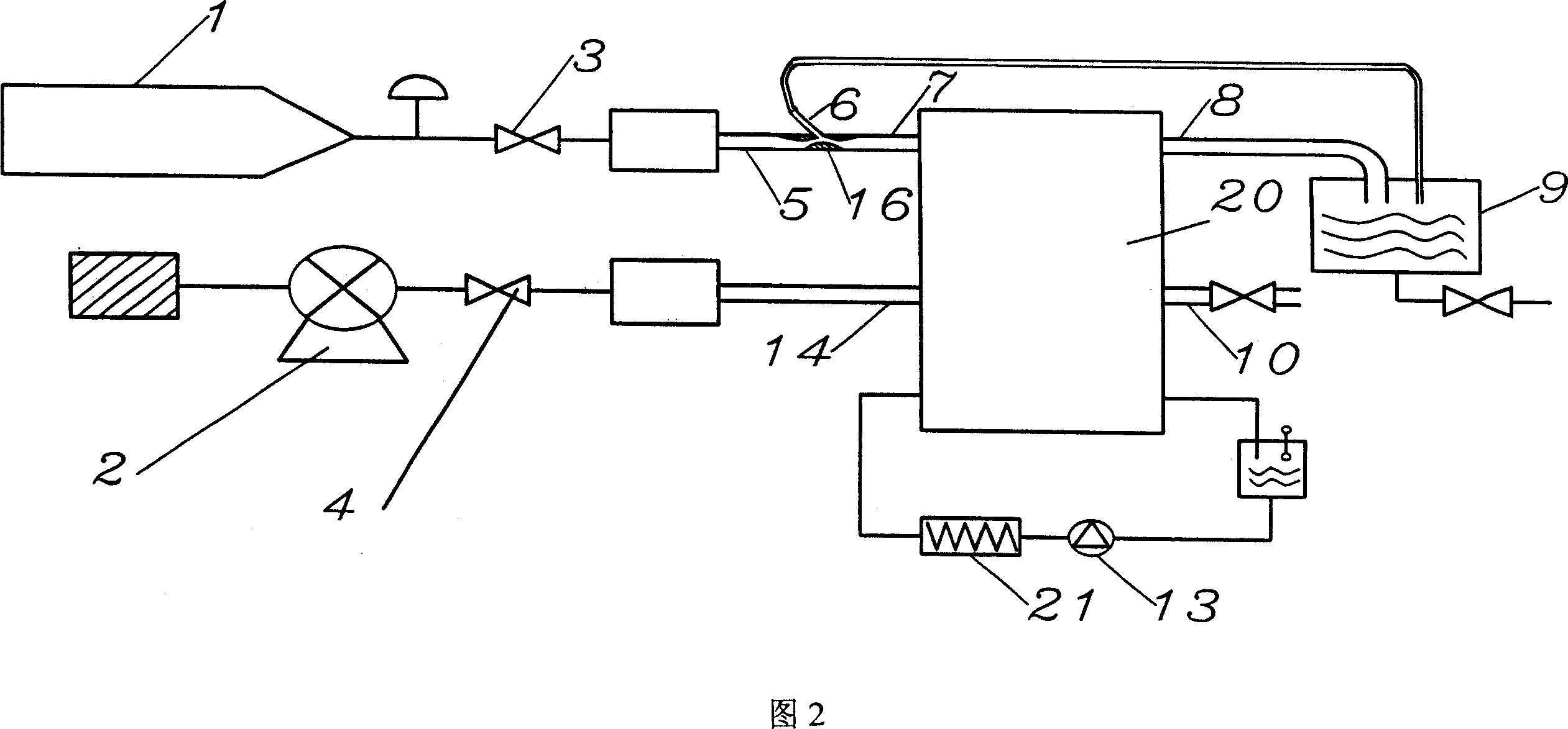
[0045] As shown in Figure 2, it is a hydrogen-air type 10-kilowatt fuel cell power generation system. Hydrogen gas at 2 to 1000 atmospheres can be stored in the hydrogen compression container 1, and the pressure can be stabilized at 0.1 to 5 atmospheres after passing through the pressure regulating and stabilizing valve 3. under some pressure. The air compression pump 2 can supply air pressure with a certain specific working pressure of 0.1 to 8 atmospheres. After the pressure regulating and stabilizing valve 4, the pressure stabilized is approximately equal to the pressure after the decompression and pressure stabilization of the above-mentioned hydrogen gas.

[0046] The hydrogen gas passes through the main supply channel pipe 5, and the flow velocity is increased at the narrow throat 16, and a vacuum suction is generated on the manifold 6. Hydrogen enters the fuel cell from the fuel cell inlet 7, and the part with a stoichiometric ratio of 1.0 participates in the electroche...

Embodiment 2

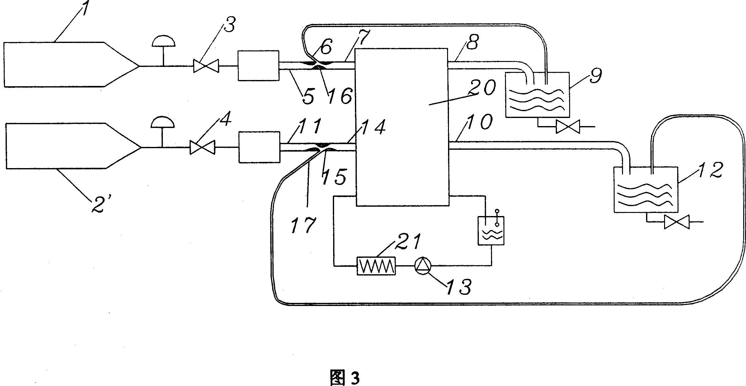
[0051] As shown in Fig. 3, it is a kind of hydrogen-oxygen type 10 kilowatt fuel cell power generation system, hydrogen compression container 1, oxygen compression container 2' each can store hydrogen and oxygen of 2 to 1000 atmospheric pressure. After the hydrogen and oxygen supply regulator valves 3 and 4 regulate and stabilize the pressure, the hydrogen and oxygen supply fuel cell pressure is stabilized at a certain pressure of 0.1 to 5 atmospheres, and the two pressures are roughly equal. Hydrogen and oxygen each pass through the supply main channel pipes 5, 11 and respectively increase their flow velocities at the narrow throats 16, 15, and respectively generate vacuum suction to the manifolds 6, 17. Hydrogen and oxygen enter the fuel cell through the inlets 7 and 14 of the fuel cell. Part of the hydrogen and oxygen with a stoichiometric ratio of 1.0 participate in the electrochemical reaction to generate water, and the fuel cell 20 outputs current and voltage to the outsi...


PUM


Abstract

This invention relates to a device for fully utilizing H2 and O2 of fuel cells including a H2 or O2 main pipeline, a H2 or O2 inlet pressure adjusting valve and a fuel cell stack, in which, the main pipeline is connected with the inlet and is set with a branch pipeline on the same direction, the other end of which is connected with the outlet of them, the inlet pressure adjusting valve adjusts the pressure of the H2 or O2 entering into the fuel cell stack to ensure that the H2 or O2 measurement ratio providing the stack is greater than 1.0 and the rest coming out from the outlet of the stack enters into the main pipeline by being absorbed by the branch one to be used in circulation.

Description

technical field [0001] The invention relates to a fuel cell, in particular to a device capable of making full use of hydrogen and oxygen in the fuel cell. Background technique [0002] An electrochemical fuel cell is a device that converts hydrogen and oxidants into electrical energy and reaction products. The internal core component of the device is the membrane electrode (Membrane Electrode Assembly, referred to as MEA). The membrane electrode (MEA) is composed of a proton exchange membrane and two porous conductive materials, such as carbon paper, sandwiched between the two sides of the membrane. On the two boundary surfaces of the membrane and the carbon paper, there are even and finely dispersed catalysts for initiating electrochemical reactions, such as metal platinum catalysts. Conductive objects can be used on both sides of the membrane electrode to draw the electrons generated during the electrochemical reaction through an external circuit to form a current loop. ...

Claims


Application Information

Patent Timeline
Patent Type & Authority Applications(China)
IPC IPC(8): H01M8/06H01M8/04H01M8/02H01M8/0297H01M8/04014H01M8/04276H01M8/0606
CPCY02E60/50
Inventor 胡里清郭伟良胡卓滔
Owner SHANGHAI MUNICIPAL ELECTRIC POWER CO
Learn More