High speed magnetic resistance motor

A reluctance motor, high-speed technology, applied in the direction of electromechanical devices, electrical components, mechanical equipment, etc., can solve the problems of unsatisfactory synchronization performance, low efficiency and power factor, and small stable operation range of the motor, so as to increase the effective thermal conductivity of the space , good synchronization performance, simple and compact structure

Inactive Publication Date: 2007-06-27
INST OF ELECTRICAL ENG CHINESE ACAD OF SCI
View PDF0 Cites 11 Cited by
  • Summary
  • Abstract
  • Description
  • Claims
  • Application Information

AI Technical Summary

Problems solved by technology

Conventional reluctance motors usually use aluminum or air gap as the rotor quadrature axis magnetic resistance material, and its output torque, power density, efficiency and power factor are...

Method used


Image

  • High speed magnetic resistance motor
  • High speed magnetic resistance motor
  • High speed magnetic resistance motor

Examples


Embodiment Construction

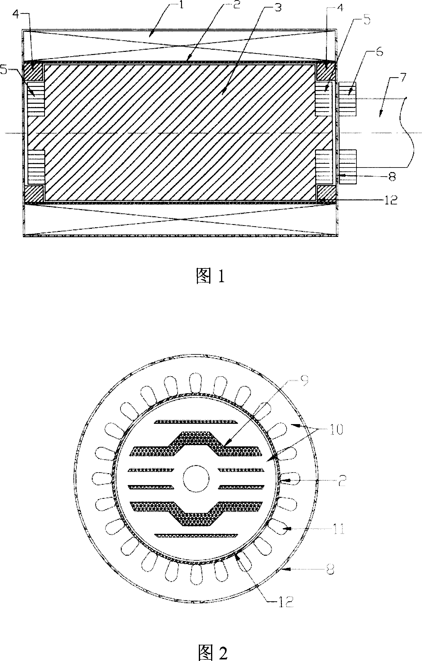
[0032] As shown in Figure 1, the motor body of the present invention consists of a superconducting or constant conducting stator 1, a nonmagnetic thin-walled metal sleeve 2, a rotor 3 embedded with superconducting blocks and strips, and an annular array of superconducting blocks 4 , permanent magnetic ring 5 and non-magnetic metal Dewar 8; high-temperature superconducting block annular array 4, permanent magnetic ring 5 and motor rotor 3 constitute a magnetic bearing; at the same time, the load side magnetic coupling 6, mechanical transmission shaft 7 Constitute the magnetic force transmission mechanism with the permanent magnet ring 5 again.

[0033] Sector-shaped permanent magnets are respectively fixed on the axial end surfaces on both sides of the rotor 3 , and are arranged regularly according to polarity to form a permanent magnet ring 5 . Two sets of ring-shaped high-temperature superconducting block arrays 4 are placed on the inner wall of the sleeve 2, and the position...


PUM


Abstract

This invention relates to a high speed magnetic resistance motor characterizing that a high temperature super conduction material is inserted in th rotor, the ab surface of the material is parallel to the rotor axes and taken as the reluctance medium to increase the reluctance difference of rectangular axis to increase output torque and power density of the motor, a high temperature super conduction block material of the internal wall of an inter-air sleeve and a magnet ring of the rotor terminal constitute a magnet floation unit to guarantee that the rotor operates at low damping and high speed, and inter-air space is filled with He or H to conduct and cool super conduction rotor, the magnet ring is acted with the coaxial semi-magnetic force coupling at the load side to realize touchless torque and power output of the motor.

Description

technical field [0001] The invention relates to a rotating electrical machine, in particular to a low energy consumption, high-speed special reluctance electrical machine. Background technique [0002] The reluctance motor is a synchronous motor that generates reluctance torque by using the difference between the reluctance values ​​of the quadrature axis and the direct axis on the rotor. Compared with the traditional synchronous motor, the rotor of the reluctance motor only has salient poles, and there is no excitation winding or permanent magnet material. It has the advantages of simple structure, no sliding contact, easy manufacture, low cost, large overload capacity, reliable operation, etc. Advantages, widely used in electric power transmission, precision control, electronic instruments and equipment and other fields. Conventional reluctance motors usually use aluminum or air gap as the rotor quadrature axis magnetic resistance material, and its output torque, power de...

Claims


Application Information

Patent Timeline
IPC IPC(8): H02K1/27H02K3/02H02K7/08H02K7/10F16C32/04
Inventor 丘明姚志豪夏东徐喆
Owner INST OF ELECTRICAL ENG CHINESE ACAD OF SCI
Why Eureka
Try Eureka