Mold assembly for forming element and forming method thereof

A mold assembly and component technology, applied in the fields of chemistry, physics, and material science, can solve problems such as mold material layer depressions, and achieve the effect of improving quality and manufacturing throughput

Inactive Publication Date: 2007-07-04
宋健民
View PDF2 Cites 2 Cited by
  • Summary
  • Abstract
  • Description
  • Claims
  • Application Information

AI Technical Summary

Problems solved by technology

Due to the dangling electrons, the reaction may cause depression of the mold material layer or DLC

Method used


Image

  • Mold assembly for forming element and forming method thereof
  • Mold assembly for forming element and forming method thereof

Examples


example 1

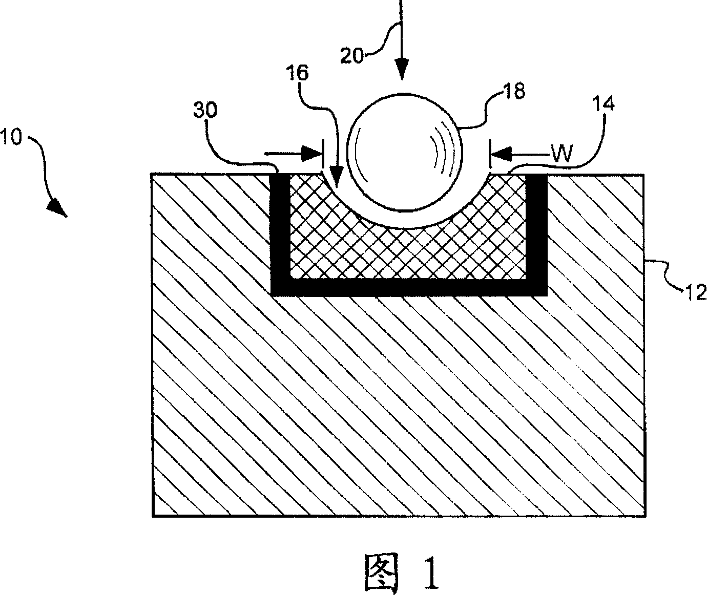
[0094] Mixing micron-sized (about 2 to 6 micron) diamonds with tungsten powder at a pressure of about 6 Gpa and a temperature of about 1500°C for 20 seconds, the resulting PCD has a cylindrical shape with a diameter of about 30 microns and a height of about 20 microns, The PCD releases electrons due to the presence of tungsten to create recesses in it, and as a result the recesses are ground by diamond tools and mirror polished by beating or grinding with reduced size diamond dust, the resulting mold can be It can be used directly or further coated with diamond film or ceramic composition.

example 2

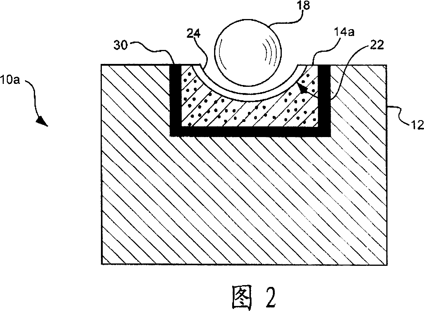
[0096] A sintered cylinder is used as the molding material layer, which is formed with recesses and a smooth finish, and its surface is covered with a ceramic composition coating, which is built flat from silicon carbide to tungsten, so that the surface has little or no grain boundaries.


PUM

PropertyMeasurementUnit
Mohs hardnessaaaaaaaaaa

Abstract

Mold assemblies for forming optical elements including a support material and a molding material are disclosed and described. In one aspect, the molding material can include a single crystal diamond coupled to the support material and includes a working surface defining a shape to be imparted to an optical element to be pressed in the mold assembly. In another aspect, the molding material can include a PCD compact coupled to the support material and includes a working surface defining a shape to be imparted to an optical element to be pressed in the mold assembly. In yet a further aspect, the molding material may include a cermet composite coating material which provides a gradient of one material coupled to the support material to another material at a working surface of the molding material which defines a shape to be imparted to an optical element to be molded. The present invention can improve the quality of the optics lens or other device and manufacturing capacity.

Description

technical field [0001] The present invention relates to a superhard working surface mold assembly for forming optical elements and other at least partially spherical elements. The invention therefore relates to the fields of chemistry, physics, and materials science. Background technique [0002] Compression molding is widely used in the manufacture of various parts that require relatively high productivity. For example, injection molding of polymer materials used to package semiconductor devices such as diodes is a routine manufacturing process, and ophthalmic lenses are also used in the same way. In recent years, relatively small camera lenses such as those used in cell phones and other similar devices have been able to be mass-produced. Such lenses may be made of transparent polymers or optical glass. In a typical application, a beaded feedstock can be flattened between two anvils to form a lens. The anvil in this procedure usually has a concave portion that is accuratel...

Claims


Application Information

Patent Timeline
Patent Type & Authority Applications(China)
IPC IPC(8): B29C33/38B29C33/00B29C43/36C03B11/08B32B33/00B32B18/00B29L11/00
CPCC03B2215/11C03B2215/12C03B2215/24C03B11/086C03B11/084C03B2215/07
Inventor 宋健民
Owner 宋健民
Why Eureka
Try Eureka