
Heat exchanger tube, method of manufacturing heat exchanger tube, and fluidized-bed furnace

A manufacturing method and technology for heat transfer tubes, applied in the field of heat transfer tubes, can solve the problems of wear, cracks, corrosion of heat transfer tubes, etc., and achieve the effect of reducing inspections

Inactive Publication Date: 2007-07-04
DOWA HLDG CO LTD
View PDF2 Cites 12 Cited by
  • Summary
  • Abstract
  • Description
  • Claims
  • Application Information

AI Technical Summary

Problems solved by technology

Under such an environment, it is difficult to make the heat transfer tube have sufficient performance. Its heat resistance to the high temperature in the fluidized bed furnace, its wear resistance Intensity of pressure generated by entry, corrosion resistance to corrosive gases, ductility that does not cause cracks even if expansion and contraction with temperature changes occur, thermal conductivity that can effectively adjust the temperature of fluid sand and incineration wait, can't satisfy
Therefore, deterioration such as wear, damage, corrosion, and cracks of the heat transfer tubes is easy to occur, and it is difficult to prolong the life of the heat transfer tubes, requiring frequent inspection, repair, and replacement of the heat transfer tubes.
It is difficult to reduce the labor and cost required for the work in this case

Method used


Image

  • Heat exchanger tube, method of manufacturing heat exchanger tube, and fluidized-bed furnace
  • Heat exchanger tube, method of manufacturing heat exchanger tube, and fluidized-bed furnace
  • Heat exchanger tube, method of manufacturing heat exchanger tube, and fluidized-bed furnace

Examples


Embodiment Construction

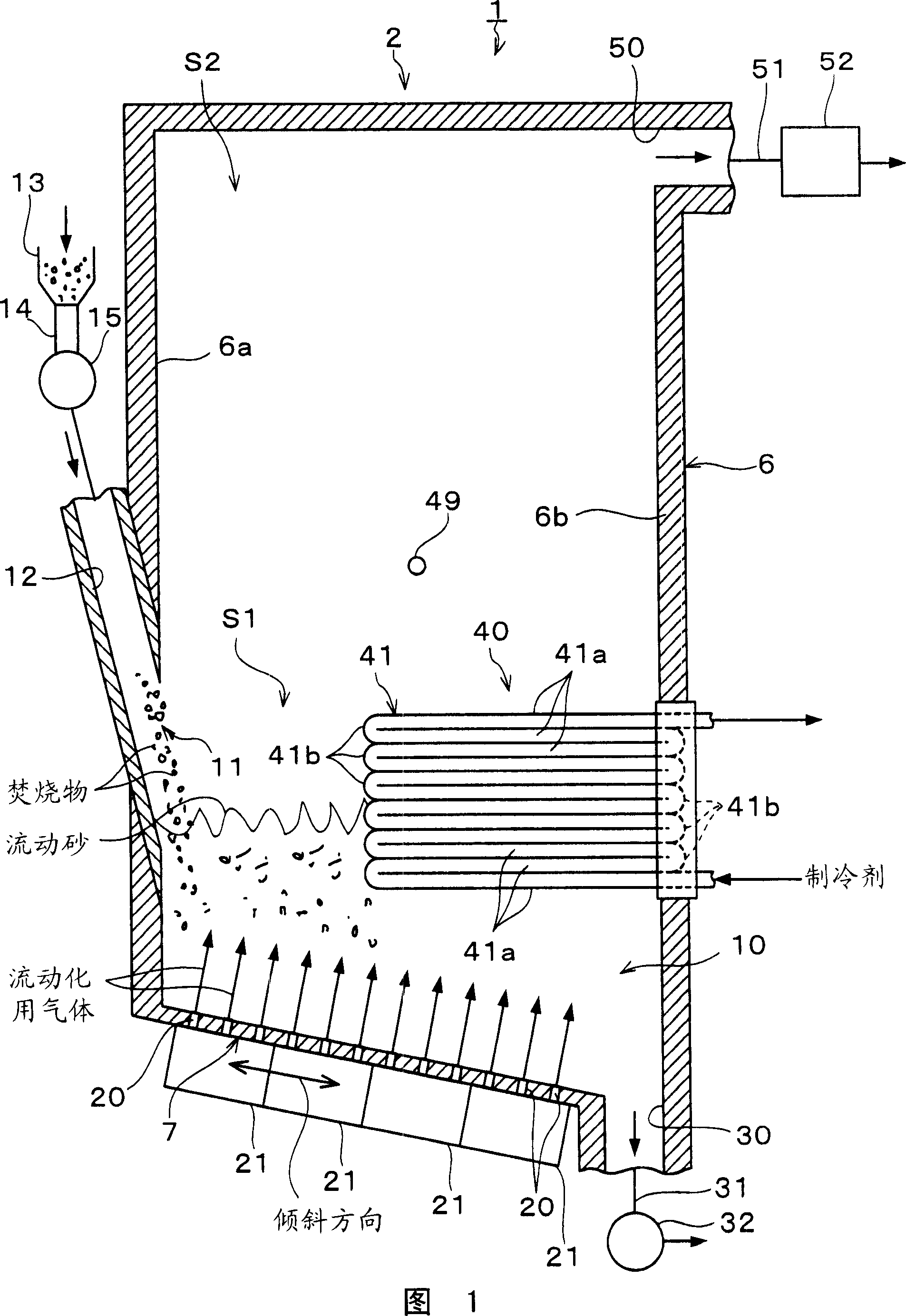
[0023] Next, preferred embodiments of the present invention will be described based on a fluidized bed furnace that incinerates shredder dust of discarded automobiles as incineration products (incineration raw materials). The fluidized bed furnace 1 shown in FIG. 1 is an inclined dispersed fluidized bed combustion furnace, and has a furnace body 2 that is approximately square. In the inner space of the furnace body 2, the lower part becomes the primary combustion chamber S1 for burning the incinerated material (primary combustion), and the upper part becomes the secondary combustion chamber for burning the exhaust gas generated by the primary combustion of the incinerated material (secondary combustion). (free space) S2.

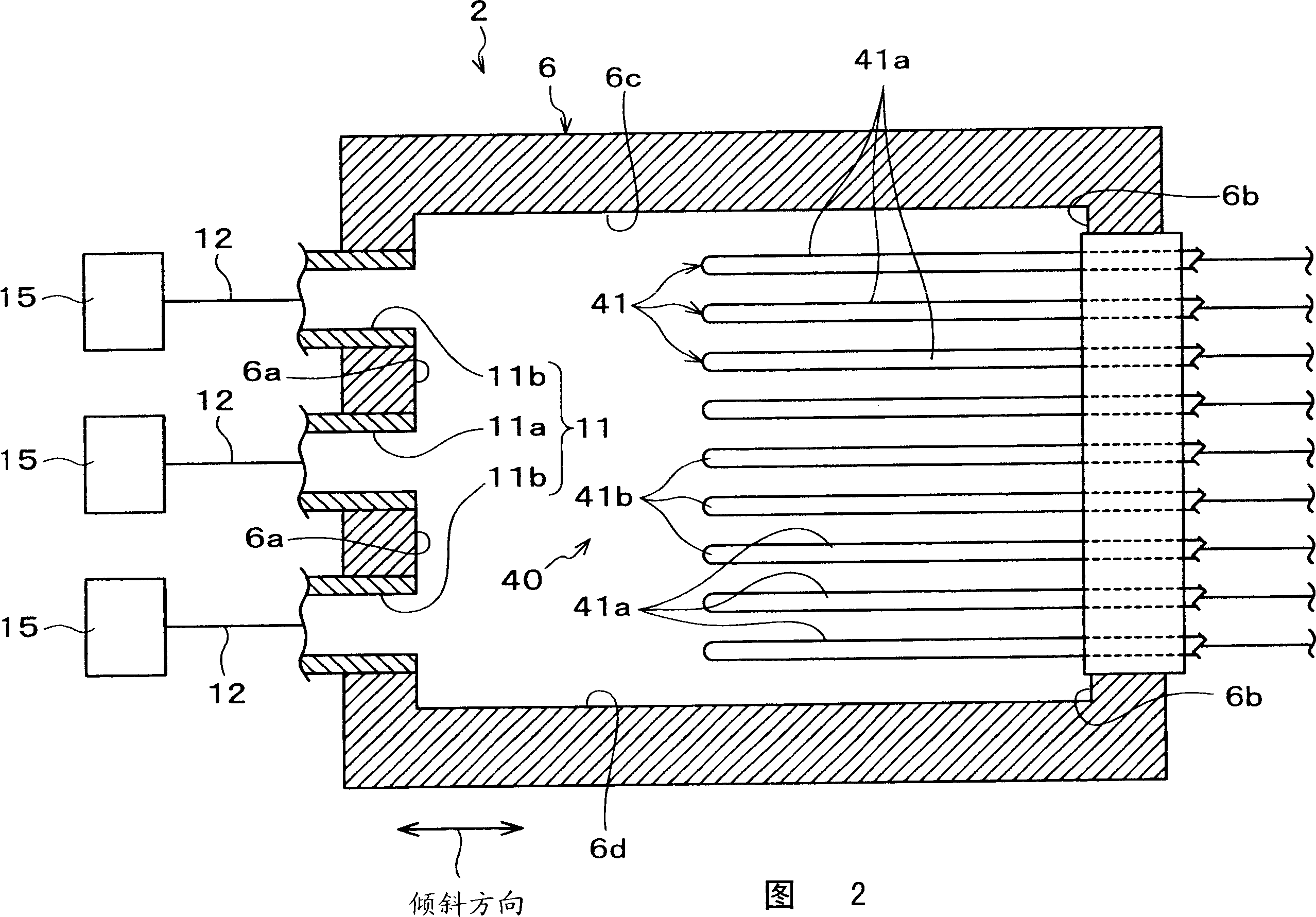
[0024] The side wall portion 6 of the furnace body 2 is approximately square cylindrical, has approximately the same cross-sectional shape as a rectangle, and has four inner sides erected in an approximately vertical direction, that is, the front inner side ...


PUM


Abstract

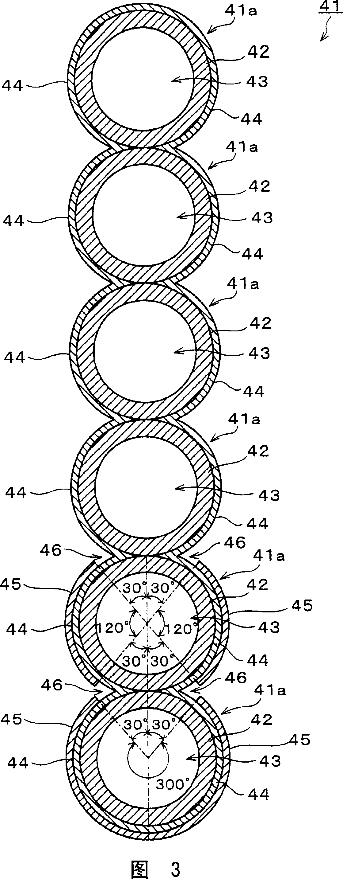
A heat exchanger tube 41 includes: a first cover layer 44 provided on an outer side of a tube main body 42 to partly or completely cover a tube main body 42; and a second cover layer 45 provided on an outer side of the first cover layer 44 to partly or completely cover the first cover layer 44. The first cover layer 44 is formed by overlay-welding a material higher in ductility than the second cover layer 45 to the tube main body 42. The second cover layer 45 is formed by overlay-welding a material higher in hardness than the first cover layer 44 to the first cover layer 44.

Description

technical field [0001] The invention relates to a heat transfer tube, a manufacturing method of the heat transfer tube and a fluidized bed furnace. Background technique [0002] A fluidized bed furnace for incinerating waste has a fluidized bed in which fluidized sand such as silica sand is deposited on the hearth. Fluidized bed furnace is a device for heating fluidized sand while blowing fluidizing gas such as air from the hearth into the fluidized bed, mixing incinerated waste such as waste with high-temperature fluidized sand, stirring and drying , Thermal decomposition, make it burn. [0003] In the furnace body of this fluidized bed furnace, heat transfer pipes (cooling pipes) for adjusting the temperature of fluidized sand and incinerated materials are provided (see JP-A-2004-93058 and JP-A-2005-315566). Refrigerant such as water circulates inside the heat transfer tube, through the fluid sand in contact with the surface of the heat transfer tube, the incineration an...

Claims


Application Information

Patent Timeline
Patent Type & Authority Applications(China)
IPC IPC(8): F28F19/00F23G5/30B23K9/04
CPCF28D13/00F28F19/06F23G2201/80F28F2225/04F23C10/18F28F2245/00F22B31/0023F23G5/48F22B37/107F23G2209/28F23G2203/50Y02P80/15
Inventor 猪股宽成吉田浩
Owner DOWA HLDG CO LTD
Learn More