
Novel prefabricated concrete hollow slab girder and construction process for building roads and bridges by using same

A hollow slab girder and concrete technology, which is used in the erection/assembly of bridges, bridge construction, joists, etc., can solve the problem of difficulty in better improving the accuracy of wedge-shaped backing plates, increasing design, construction workload, and prolonging design and construction periods, etc. problems, to shorten the design cycle, improve strength, and eliminate shear slippage

Active Publication Date: 2007-07-11
SHANGHAI URBAN CONSTR DESIGN RES INST GRP CO LTD +1
View PDF1 Cites 9 Cited by
  • Summary
  • Abstract
  • Description
  • Claims
  • Application Information

AI Technical Summary

Problems solved by technology

[0009] The technical solution of this utility model can better solve the force balance problem between the support surface and the beam bottom when it is implemented, but since each wedge-shaped backing plate needs to be calculated separately according to the terrain parameters and the calculation is complicated, it obviously increases The workload of design and construction greatly prolongs the design and construction period, and it is difficult to better improve the accuracy of the wedge-shaped backing plate
[0010] At the same time, because the above-mentioned wedge-shaped backing plate and the slab girder constituting the road and bridge deck are designed and constructed separately, after a certain period of use due to factors such as changes in stress conditions, shearing and sliding are easily formed between the two and are damaged, making the road and bridge shortened service life

Method used


Image

  • Novel prefabricated concrete hollow slab girder and construction process for building roads and bridges by using same
  • Novel prefabricated concrete hollow slab girder and construction process for building roads and bridges by using same
  • Novel prefabricated concrete hollow slab girder and construction process for building roads and bridges by using same

Examples


Embodiment Construction

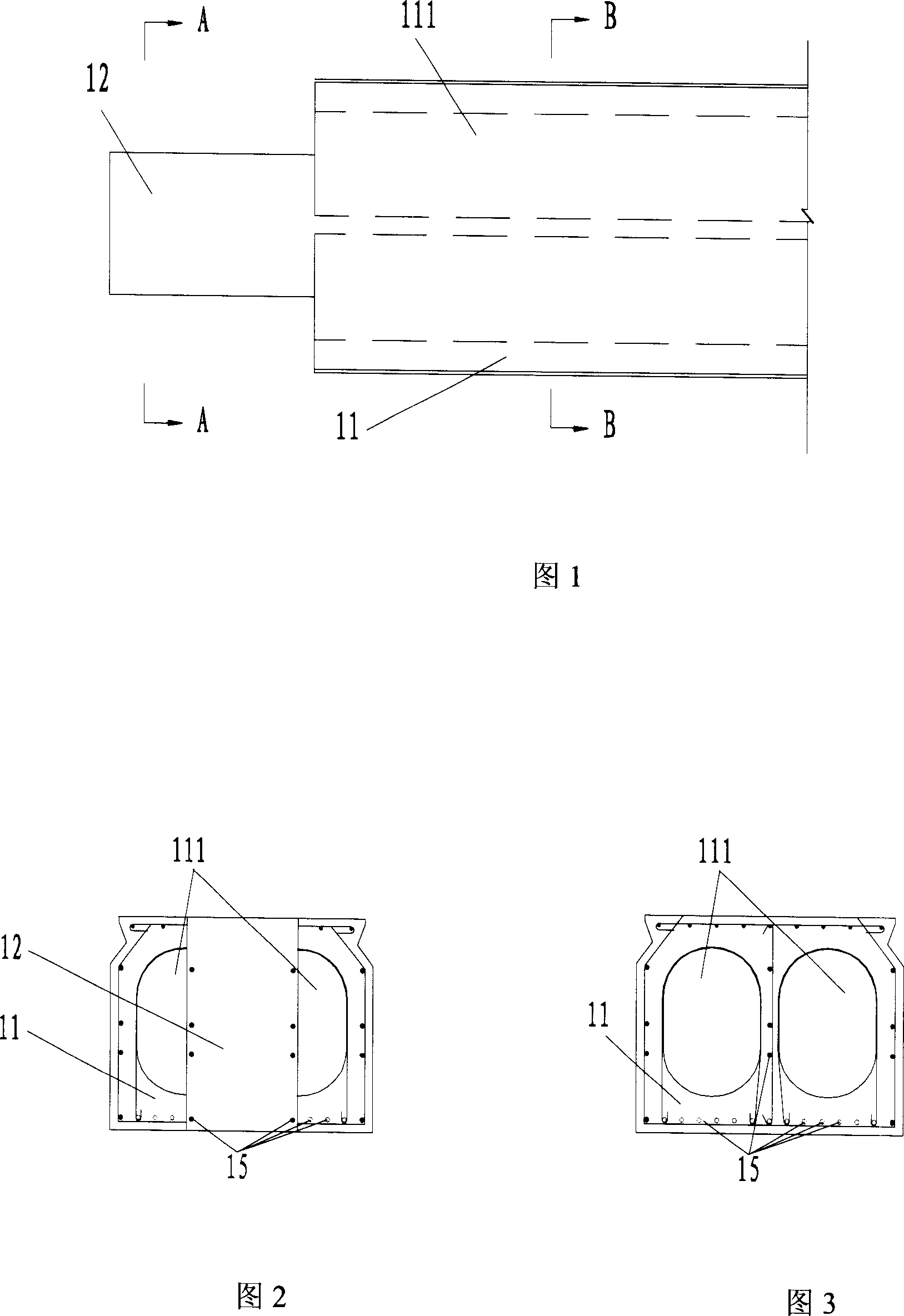
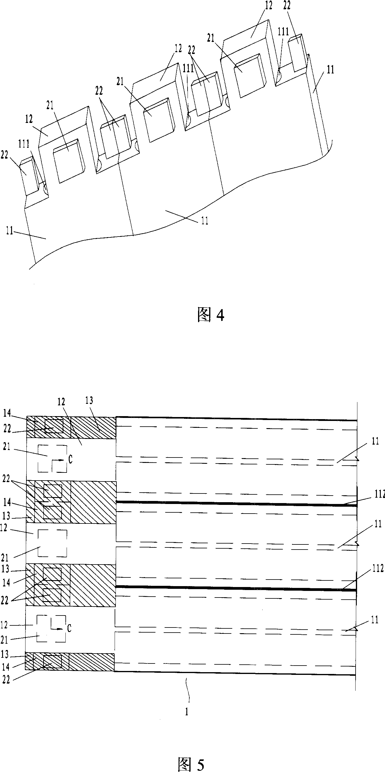
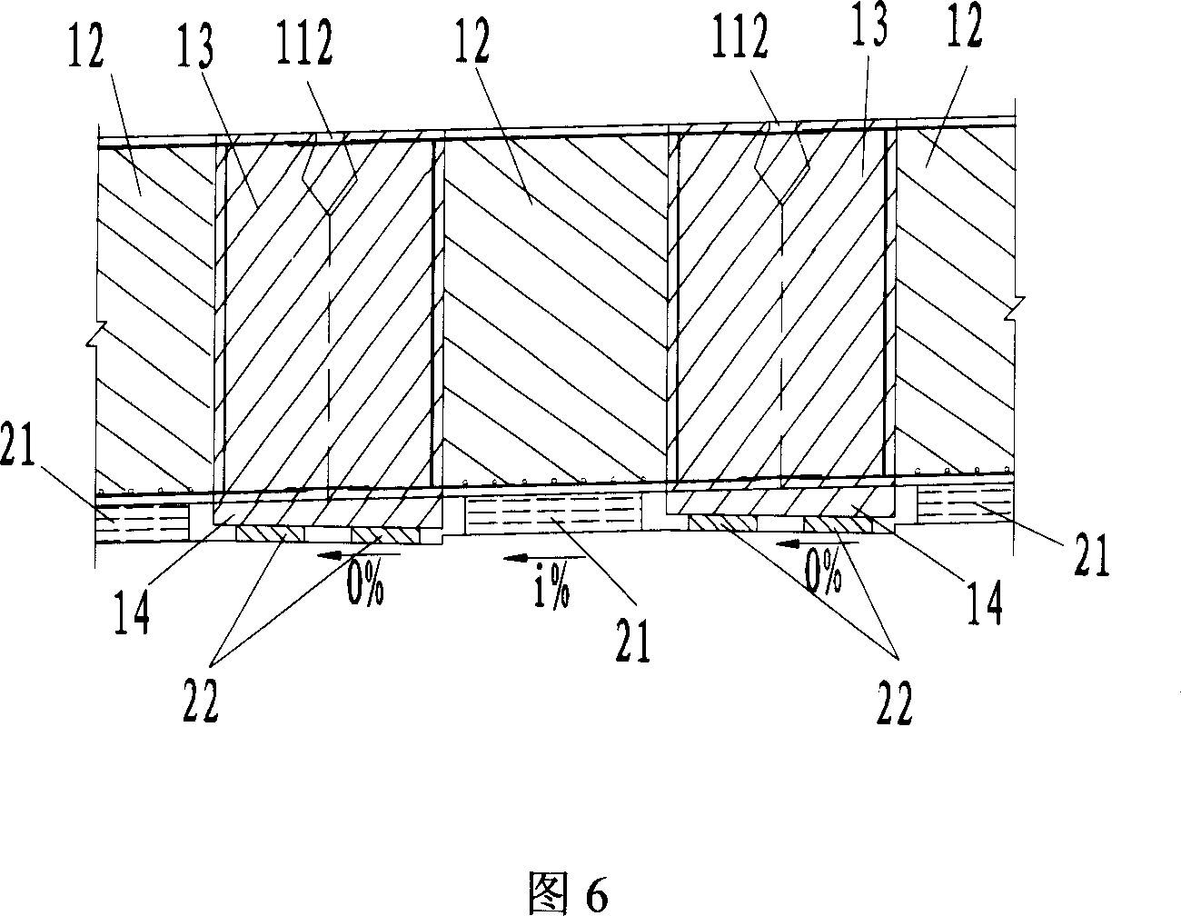
[0037] As shown in Figure 1, it is a specific embodiment of the novel prestressed concrete hollow slab girder of the present invention, the material of the hollow slab girder is prestressed reinforced concrete, comprises a quadrangular body 11, and the top surface of the body 11 is roughly smooth, and There is a through cavity 111 inside, and the two ends 12 respectively located at the two ends of the body 11, the two ends 12 and the body 11 are integrally formed, and the prestressed steel bars are pre-embedded continuously in the body 11 and the two ends 12 15. Since the shapes and forces of the two ends 12 in this embodiment are symmetrically the same, only the ends 12 will be described below.

[0038] As shown in Fig. 1, Fig. 2 and Fig. 3, the end 12 is tenon-shaped, protrudes about 1 meter from the body, and is a solid body, and its top and bottom surfaces are flush with the top and bottom surfaces of the body 11. The width of the end 12 is slightly less than half of the ...


PUM


Abstract

The invention discloses a novel prestressed concrete hollow slab beam, comprising a hollow cubic body, two heads. Two ends are integrated with the body and steel bar is pre-buried in it. The head is rabbet solid body. The invention also discloses a construction process for roads and bridges adopting said hollow slab beam. Relative temporary supports are set on the top of capping beam or abutment. The hollow slab beam is set on temporary supports. Fixed supports are set on the top of capping beam or abutment; pre-buried steel bars between adjacent heads and in body are connected; the cast-in-case concrete connecting part and integrated padding block for connecting the body and adjacent heads are cast in scene so that padding block is set on the fixed support in horizon. Said procedures are iterated so that the surface of road and bridge is connected by hollow slab beam. Because special designing slab beam and step pouring technology are adopted in the invention, the demand of prior new criterion is satisfied expediently. At the same time integrity and durability of slab beam are strengthened and the period of design and construction is shortened.

Description

technical field [0001] The invention relates to the field of road and bridge construction, in particular to a prestressed concrete hollow slab girder, and also relates to a construction technique for erecting a road and bridge by using the hollow slab girder. technical background [0002] In the field of construction, hollow-core slab girders are frequently used in bridge and road construction. However, the hollow slab girders in the prior art often suffer from some diseases during the use of bridges and roads, and also include some inconveniences in design and construction, such as: [0003] a. Due to various factors such as the load from the hollow slab beam road, the upper part of the bridge, the penetration and corrosion of bridge deck rainwater, and careless construction, the hinge joints between the hollow slab girders are easy to break after a period of use, forming a single beam. , which accelerates the damage of the bridge structure; [0004] b. As rainwater infil...

Claims


Application Information

Patent Timeline
Patent Type & Authority Applications(China)
IPC IPC(8): E04C3/26E01D21/00E01D2/00E01D101/28
Inventor 刘晓苹黄锦源李艳吴刚
Owner SHANGHAI URBAN CONSTR DESIGN RES INST GRP CO LTD
Learn More