Wave-structured film beam polarizer

A polarizing device and wave-like technology, applied in the field of wave-like structure thin-film beam polarizers, can solve the problems of complex processing technology and high investment cost, and achieve the effect of wide selection of materials, low production cost and high degree of polarization

Inactive Publication Date: 2007-07-11
ZHEJIANG UNIV
View PDF2 Cites 2 Cited by
  • Summary
  • Abstract
  • Description
  • Claims
  • Application Information

AI Technical Summary

Problems solved by technology

Their basic principles are to use the bandgap structure of photonic crystals to polarize beams. The disadvantage is that the processing technology of the periodic microstructures of two-dimensional photonic crystals is complicated, especially in the light wave band, where the size of the microstructures reaches the submicron level. Expensive high-precision manufacturing equipment, the investment cost is too high

Method used


Image

  • Wave-structured film beam polarizer
  • Wave-structured film beam polarizer
  • Wave-structured film beam polarizer

Examples


Embodiment 1

[0016] Example 1: Wavy Structure Thin Film Beam Polarizer at Normal Incidence

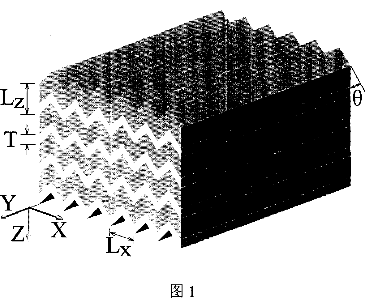
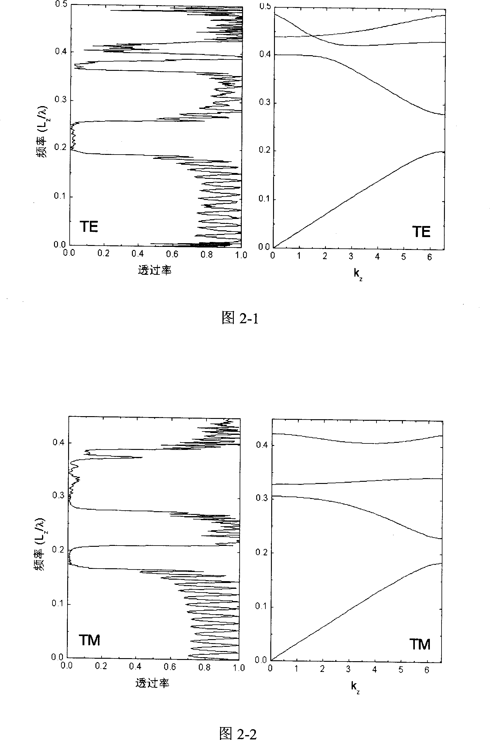
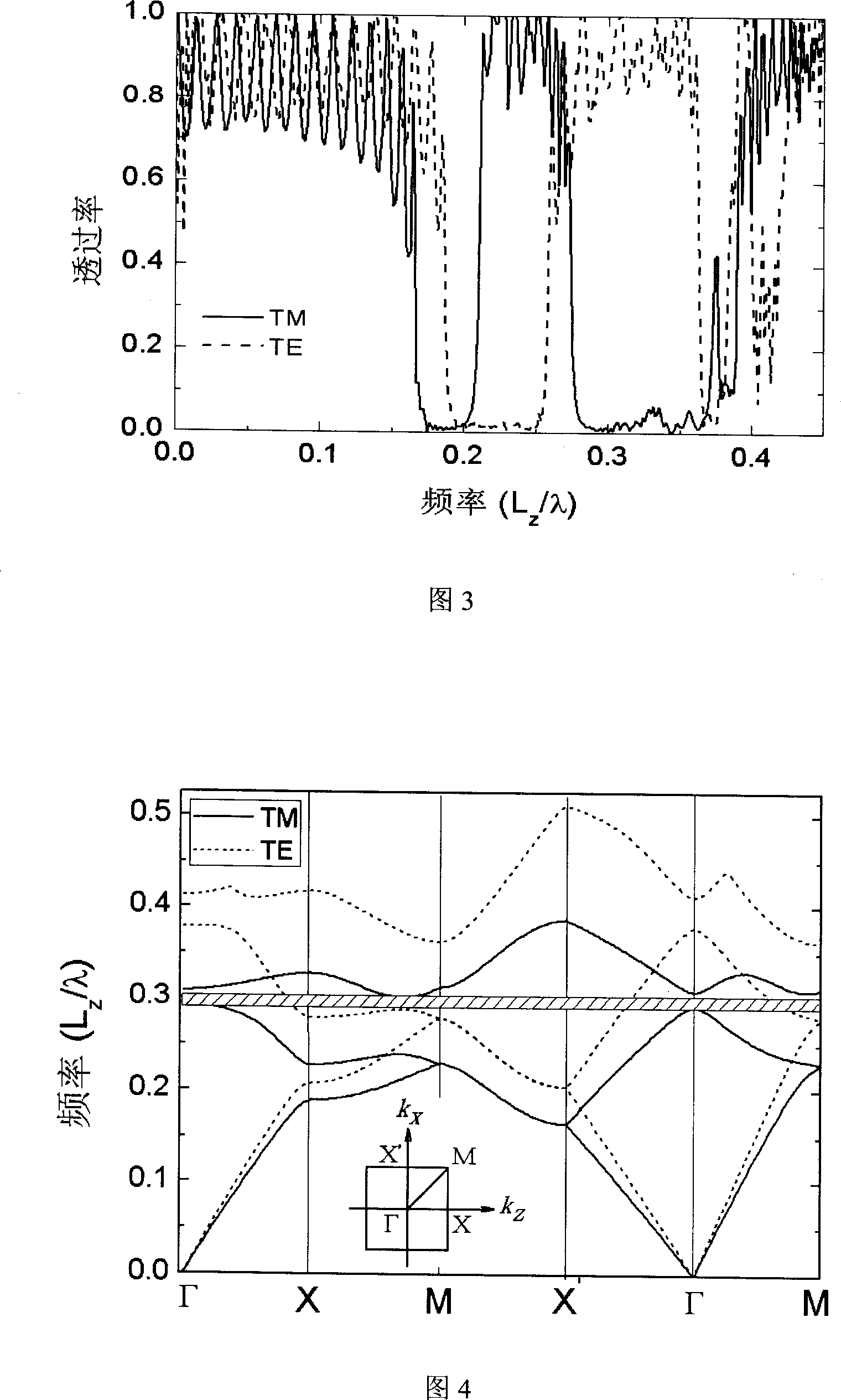
[0017] The wavy structure film is shown in Figure 1, and the period L of the film layer along the Z direction z Take it as 480nm, the thickness T of the high refractive index material is taken as 160nm, and the period L of the wavy structure along the X direction x Take it as 560nm, take the inclination angle θ of the wavy film layer as 45 degrees, and choose Si (n=3.5) and SiO as the two dielectric materials respectively. 2 (n=1.5), the beam is incident vertically along the Z axis. Figure 2 shows the transmission spectra of TE mode and TM mode and their corresponding energy band structures. Figure 3 shows the comparison of the transmission spectra of the two polarization states, at L z / λ=0.165-0.18 and L z / λ=0.275-0.36 In the two frequency bands, the TE mode is highly transparent and the TM mode is reflected. z / λ=0.21-0.255 In the frequency band, the TE mode is reflected and the TM mode is...

Embodiment 2

[0018] Example 2: Wave-structured thin-film beam polarizer at oblique incidence

[0019] The wavy structure film is shown in Figure 1, L z Take it as 440nm, T as 140nm, L x Take it as 560nm, take θ as 45 degrees, and choose Si(n=3.5) and SiO as the two dielectric materials respectively 2 (n=1.5). Figure 4 shows the energy band structure of TE mode and TM mode, and the complete band gap of TM mode is at L z / λ=0.29-0.30. On the boundary of the first Brillouin zone (that is, X-M-X'), the second energy band of the TE mode is located below the complete forbidden band of the TM mode, and any point connected to the center Γ on the boundary represents any wavy structure inside the film. For a wave vector direction, it is known that the eigenfrequencies of the TE mode corresponding to the Γ point and the point on the boundary are respectively above and below the complete forbidden band of the TM mode. The energy band must pass through the complete forbidden band of the TM mode. S...


PUM


Abstract

The invention relates to a wave structure thin film component for optical polarization beam splitting. The multi-layer wave like thin film formed new polarized component uses the media materials with two different refraction rates and proper wave like film structure parameter required optical wave polarization feature. It expands the incidence angle of the polarization component with fully banned or fully through concept, allowing the wave structure thin film polarization component having polarized beam splitting function. It makes the polarization component with high polarization, wide material selection range, low making cost, heat resistant, with less optical consumption, adjustable incidence angle and frequency.

Description

Technical field [0001] The invention relates to a beam polarizer, in particular to a beam polarizer with a wavy structure film. Background technique [0002] A polarizer is a device that converts natural light into polarized light. Traditional polarizers made of one-dimensional optical films rely on Brewster's angle and need to be used in conjunction with glass prisms. If the incident angle deviates from the Brewster's angle, the degree of polarization will drop significantly. Uniaxial birefringent crystals can also separate o-light and e-light, but it has limitations on the range of incident angles, and the volume of the device is often large. Some crystals and polymer materials can selectively absorb light with different polarization directions by using dichroism. Because they work in absorption mode, they are not suitable for strong light applications. These traditional polarization devices are difficult to be applied in modern integrated optics. [0003] Chinese paten...

Claims


Application Information

Patent Timeline
IPC IPC(8): G02B5/30G02F1/01
Inventor 厉以宇顾培夫王元
Owner ZHEJIANG UNIV
Why Eureka
Try Eureka