Direct drive permanent magnet synchronous motor for screw pump

A permanent magnet synchronous, screw pump technology, applied in synchronous motors with stationary armatures and rotating magnets, electric components, machines/engines, etc., can solve problems such as insurmountable defects, waste of resources, inability to adjust torque, etc. Achieve the effect of preventing oil leakage from packing, high power utilization efficiency, and solving pump rod fractures

Active Publication Date: 2007-07-11
HANGZHOU XO ELEVATOR
View PDF3 Cites 12 Cited by
  • Summary
  • Abstract
  • Description
  • Claims
  • Application Information

AI Technical Summary

Problems solved by technology

The disadvantages of this structure are: 1. Low transmission efficiency and high energy consumption. This is because the screw pump generally starts at full load and operates at light load.
In order to overcome the mechanical loss in belt transmission or gear transmission and ensure a sufficient torque when starting, people usually adopt the method of increasing the motor capacity, thus causing a waste of resources for large horse-drawn carts
2. It is impossible to prevent mechanical accidents from breaking the pump rod. This is because the equipped motor is generally controlled by asynchronous constant frequency and constant pressure, and the torque cannot be adjusted. Faults such as breakage of the pump rod and breakage of the gearbox gear
3. The oil leakage of the packing is serious. Due to the use of medium and high-speed asynchronous motors and belt drives, the mechanical vibration is large, and the reduction box is driven by one-sided asymmetry, resulting in a large amplitude of the mechanical swing of the drive system. As a

Method used


Image

  • Direct drive permanent magnet synchronous motor for screw pump
  • Direct drive permanent magnet synchronous motor for screw pump
  • Direct drive permanent magnet synchronous motor for screw pump

Examples


Embodiment Construction

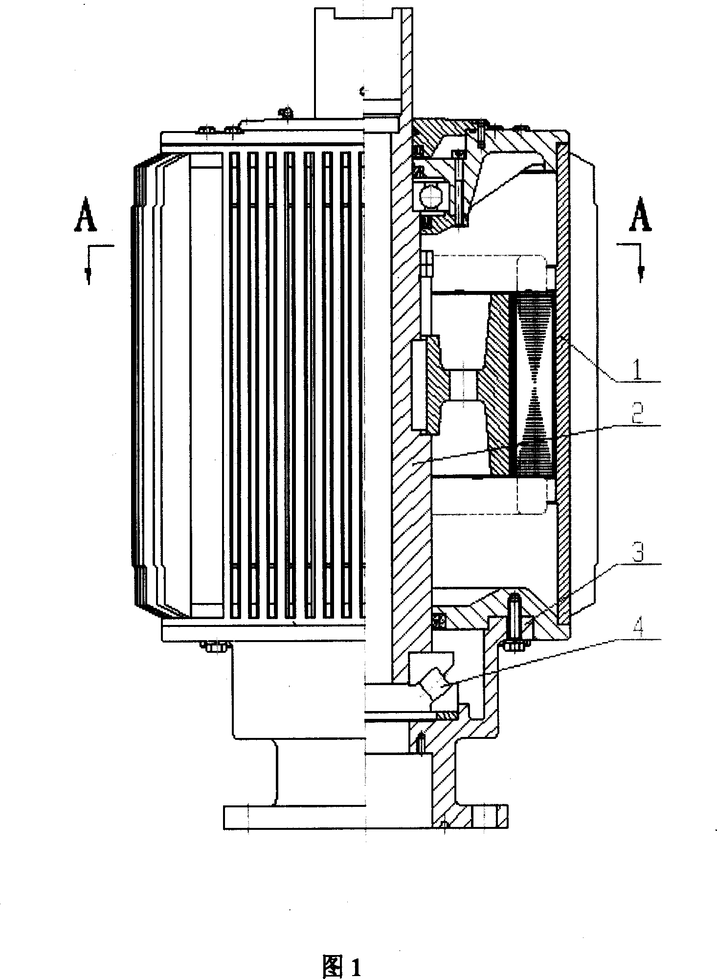
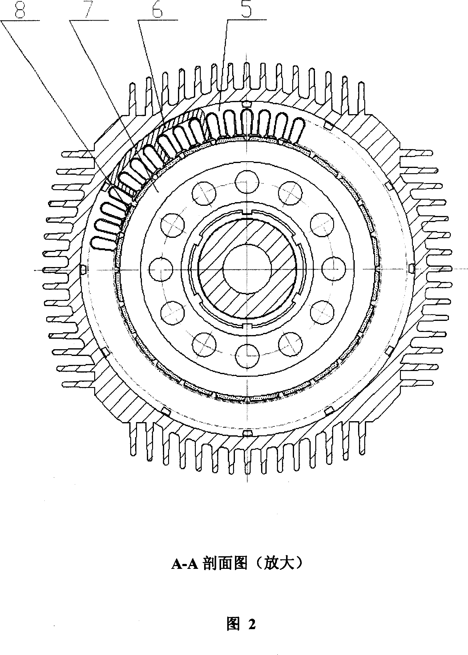
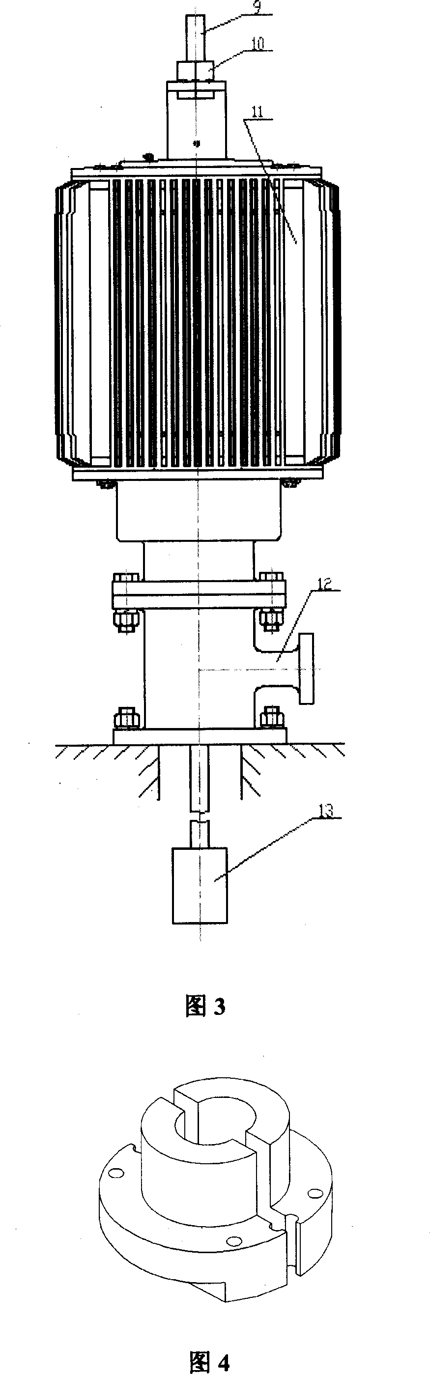
[0018] Accompanying drawings 1 and 2 are the best implementation modes of the present invention, Fig. 3 is a schematic structural diagram of the present invention after installation, and Fig. 4 is a schematic structural diagram of the split-type clip key sleeve 10 in Fig. 3 . Marked in the figure: 1. Motor casing, 2. Rotor shaft, 3. Support seat, 4. Thrust self-aligning roller bearing, 5. Stator, 6. Magnetic-sensitive position sensor, 7. Rotor, 8. Magnetic steel, 9. Polished rod, 10. Split clamp key sleeve, 11. Motor, 12. Wellhead tee, 13. Screw pump.

[0019] The detailed technical contents and implementation methods of the present invention will be further described below in conjunction with the accompanying drawings.

[0020] The direct-drive permanent magnet synchronous motor used in the screw pump of the present invention comprises permanent magnet synchronous motor parts, such as: a motor casing, a stator, a rotor, a rotor shaft, a support seat, and a thrust self-alignin...


PUM


Abstract

This invention relates to screw bar pump direct drive permanent simultaneous motor in the earth drive mechanic oil sampling device, which comprises permanent magnetic simultaneous motor and the device matched with screw pump, wherein, the invention is characterized by the following: its axis down part uses push force for roller bearing; the drive device uses permanent simultaneous motor matching with connection device meshed with screw bar. This invention saves the band transmission and gear deceleration case to provide torque times more than four times.

Description

technical field [0001] The invention relates to a direct-drive permanent-magnet synchronous motor for a screw pump, a drive device for a ground-driven screw pump, and belongs to mechanical oil recovery equipment. Background technique [0002] There are usually two driving methods for the screw pump oil production equipment driven by the ground: 1. The traditional screw pump pumping unit driven by a horizontal asynchronous motor, which uses 90° bevel gears to reduce the direction and drive the belt to increase the torque. The disadvantages of this structure are: 1. The transmission efficiency is low and the energy consumption is high. This is because the screw pump generally belongs to the full-load start-up and light-load operation state. In order to overcome the mechanical loss in belt transmission or gear transmission and ensure a sufficient torque when starting, people usually adopt the method of increasing the motor capacity, thus causing a waste of resources for large h...

Claims


Application Information

Patent Timeline
IPC IPC(8): H02K7/14H02K21/12H02K1/27F04B35/04E21B43/00
Inventor 鲁力李创平
Owner HANGZHOU XO ELEVATOR
Why Eureka
Try Eureka