
Structural foam and manufacture thereof

a structural foam and anisotropy technology, applied in the field of anisotropy structural foam, can solve the problems of difficult and time-consuming modification of the polymer composition of the foam, exhibit some degree of anisotropy, and are usually not controlled, so as to improve static mechanical properties, enhance anisotropy index, and enhance mechanical properties

Inactive Publication Date: 2018-07-10
GURIT (UK) LTD
View PDF25 Cites 1 Cited by
  • Summary
  • Abstract
  • Description
  • Claims
  • Application Information

AI Technical Summary

Benefits of technology

The present invention is a method to modify the cellular microstructure of a commercial foam called Corecell, which can enhance its mechanical properties. This is done by controlling the degree of anisotropy in the foam's cellular structure. The foam is cooled under vacuum to prevent collapse and a negative pressure is applied to expand it. This results in a foam with improved mechanical properties, such as compression strength, shear strength, and shear modulus. The invention allows for enhanced mechanical properties without changing the foam's chemical composition or using a more rigid cross-linked polymer that typically results in a more brittle foam. By introducing an AI of greater than 1 and typically less than 1.5 into the foam, its technical and commercial competitiveness can be extended without reformulation or chemical modification of the foam's chemical composition.

Problems solved by technology

It is both difficult and very time consuming to modify the polymer composition of the foam in an attempt to modify the mechanical properties of the foam to a selected target.
Most currently available foams exhibit some degree of anisotropy, but this is usually not controlled and is a direct result of the manufacturing process used to produce the foam.
Foams manufactured by continuous extrusion techniques, often have AI <1, as they tend to be susceptible to cellular alignment in the extrusion direction.
However, this would be a laborious and expensive manufacturing technique.
None of these documents discloses the production of anisotropic foams or addresses the problem of producing foams having high shear strength and stiffness, and high compressive modulus and high shear modulus.

Method used


Image

  • Structural foam and manufacture thereof
  • Structural foam and manufacture thereof
  • Structural foam and manufacture thereof

Examples


example 1

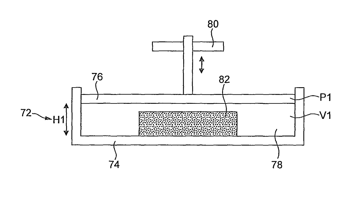
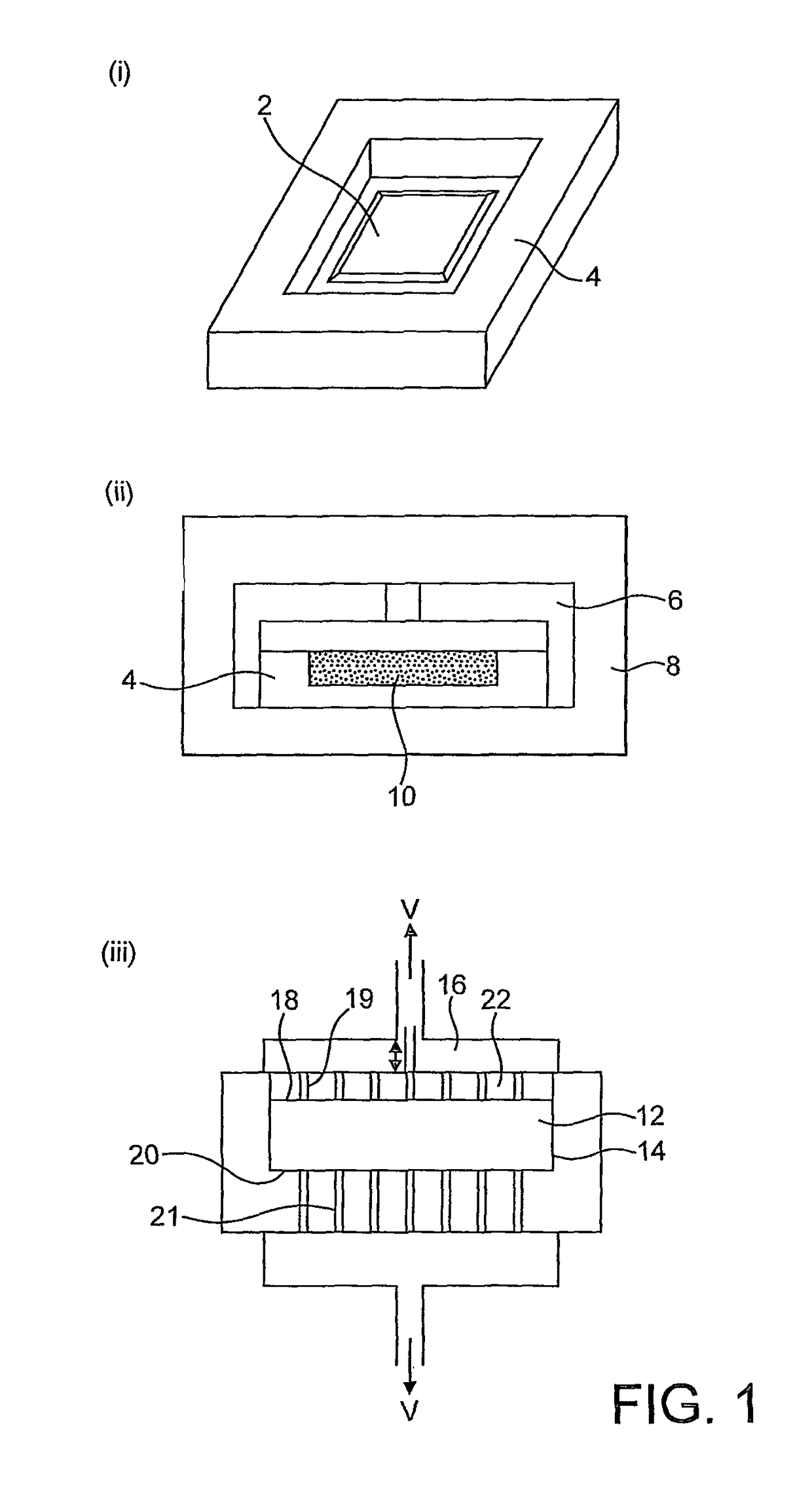
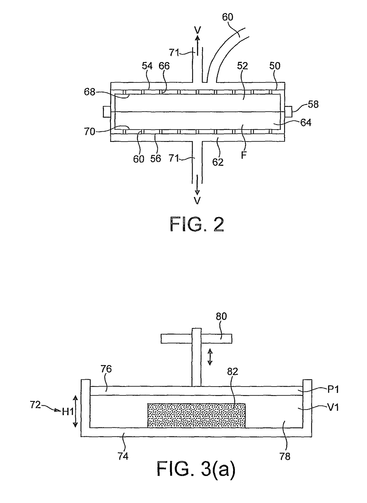
[0091]In this example, foam embryos of a styrene-acrylonitrile (SAN) polymer, similar to the polymer employed to manufacture the applicant's Corecell (Registered Trade mark) structural foam were prepared. The embryos also contained a blowing agent, comprising azobisisobutyronitrile (AZDN) and acetone. The embryos were cut to a predetermined rectangular shape and size and mounted within a mould, disposed within a hydraulic press, that was shaped and dimensions so as to determine a maximum dimension for the width and length, in the horizontal direction, of an expanded foam body formed within the mould from the embryo. In order to reach the desired value of anisotropy index, a restriction system was provided to prevent any gain in length and width of the embryo sample while it was heated and expanded to form the expanded foam body. The samples were left in the hydraulic press for a certain period at a given temperature to achieve the required expansion defined by the limits of the moul...


PUM

PropertyMeasurementUnit
pressureaaaaaaaaaa
temperatureaaaaaaaaaa
pressureaaaaaaaaaa

Abstract

A method of manufacturing a foam body having an anisotropic cell structure, the method including the steps of: expanding a polymer at an elevated temperature to form an initial foam body; and cooling the initial foam body under a negative pressure. There is also provided a method of manufacturing a foam body having an anisotropic cell structure, the method including the steps of: (a) in a first expansion step, expanding a foamable polymer composition substantially isotropically to form an initial foam body having an isotropic cell structure; and (b) in a second expansion step, expanding the initial foam body anisotropically in a selected direction under a negative pressure which applies an expanding force in the selected direction to provide a final foam body having an anisotropic cell structure. Apparatus for the methods are also disclosed.

Description

FIELD OF THE INVENTION[0001]The present invention relates to anisotropic structural foam and to an apparatus and a method for manufacturing such a foam.BACKGROUND[0002]Structural foams are used in composite sandwich panels, with the foam sheet sandwiched between opposite outer skins of fibre composite material, to maximise the thickness of the composite sandwich panels, and consequently the panel stiffness, with minimum effect on panel weight. A sandwich panel can be likened to a steel I-beam in which the composite skins act as the I-beam flanges and the core material of structural foam acts as the shear web of the beam. During bending, one skin of the panel is put into compression and the opposite skin is put into tension. This induces a shear loading in the core material. Accordingly, the shear strength and stiffness are critical properties of the core material to prevent excessive deflection and maintain structural integrity.[0003]A high compressive modulus can help prevent local...

Claims


Application Information

Patent Timeline
Patent Type & Authority Patents(United States)
IPC IPC(8): B29C44/34B29C44/58B29C44/56B29C44/08B32B3/26B29K105/04
CPCB29C44/352B29C44/083B29C44/3403B29C44/353B29C44/586B29C44/5627Y10T428/26B29C44/3423B29C2791/006B29K2105/04C08J9/00
Inventor SIMARD, YANLALANCETTE, ERICJONES, DANIEL THOMAS
Owner GURIT (UK) LTD
Learn More