Electrophotographic member, developing apparatus and image forming apparatus

a technology of developing apparatus and developing member, applied in the direction of electrographic process apparatus, instruments, optics, etc., can solve the problems of developer adhering to the surface of the member, unintentional dumping of residual developer on the non-image portion, etc., to prevent the generation of fogging and high quality

Active Publication Date: 2018-07-24
CANON KK
View PDF18 Cites 5 Cited by
  • Summary
  • Abstract
  • Description
  • Claims
  • Application Information

AI Technical Summary

Benefits of technology

[0007]One aspect of the present invention is directed to providing an electrophotographic member which can prevent generation of fogging while high quality images can be output during long-term use.
[0008]Another aspect of the present invention is also directed to providing a developing apparatus and an image forming apparatus which enable formation of high quality electrophotographic images.

Problems solved by technology

As result, the residual developer is unintentionally disposed on the non-image portions in the next developing step to generate fogging.
To meet the requirements on the developing member and the charging member described above, the developer adhering to the surfaces of these members is an obstacle in demonstration of the effects to be provided by these members.

Method used


Image

  • Electrophotographic member, developing apparatus and image forming apparatus
  • Electrophotographic member, developing apparatus and image forming apparatus
  • Electrophotographic member, developing apparatus and image forming apparatus

Examples


production example 1

Preparation of Developer A

[0113]A mixture containing the materials shown in Table 1 below was added dropwise to 200 parts by mass of cumene refluxed (temperature: 148° C. to 156° C.) over 4 hours to complete solution polymerization under refluxing of cumene. Cumene was removed while the system was being heated to 200° C. under reduced pressure.

[0114]

TABLE 1MaterialsParts by massStyrene68Butyl acrylate14Monobutyl maleate10Di-tert-butyl peroxide0.8

[0115]30 parts by mass of the resulting styrene-acrylic copolymer was dissolved in a mixture of other six materials shown in Table 2 below to prepare a mixed solution.

[0116]

TABLE 2MaterialsParts by massStyrene-acrylic copolymer30Styrene48Butyl acrylate22Monobutyl maleate2Divinylbenzene0.4Benzoyl peroxide0.7tert-Butylperoxy-2-ethylhexanoate0.7

[0117]0.15 parts by mass of partially saponified product of poly(vinyl alcohol) was dissolved in 170 parts by mass of water to prepare a solution. This solution was added to the mixed solution, and was v...

production example 2

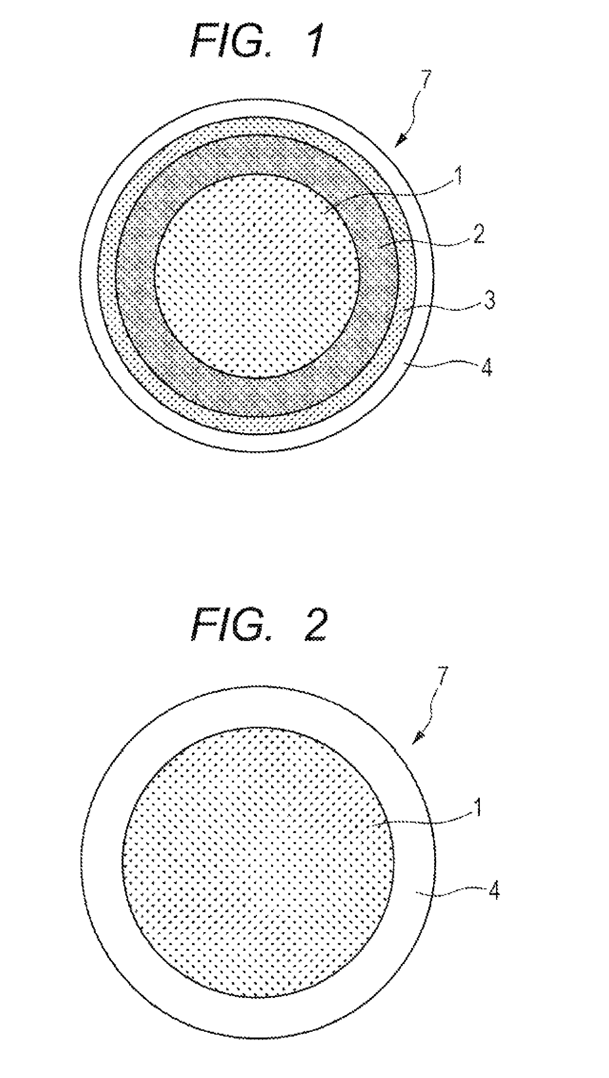
Preparation of Elastic Layer 1

[0120]Primer (tirade name: DY35-051, manufactured by Dow Corning Toray Ltd.) was applied to a cylindrical aluminum tube ground into an outer diameter of 10 mm and an arithmetic average roughness Ra of 0.2 μm, and was burned to prepare a substrate. This substrate was disposed in a metal mold, and an addition silicone rubber composition containing a mixture of the materials shown in Table 4 below was injected into the cavity formed in the metal mold.

[0121]

TABLE 4MaterialsParts by massAddition curable liquid silicone rubber material100(Trade name: SE6724A / B, manufactured by DowCorning Toray Co., Ltd.)Carbon black15(Trade name: TOKABLACK #4300, manufactured byTokai Carbon Co., Ltd.)Silica powder as heat resistant agent0.2(Trade name: AERSIL RX200*, manufactured byNIPPON AEROSIL CO., LTD.)Platinum catalyst0.1(Trade name: SIP6832.2, manufactured by Gelest Inc.)

[0122]The metal mold was then heated to vulcanize silicone rubber at a temperature of 50° C. for 15 ...

production example 3

Preparation of Intermediate Layer Roller

[0123]The materials for a layer having an irregular surface shown in Table 5 below were mixed.

[0124]

TABLE 5MaterialsParts by massPolyester polyol100(Trade name: NIPPOLAN 3027, manufactured byTosoh Corporation,Acid value: 1 or less, Hydroxyl value: 43 to 49)Isocyanate120(Trade name: CORONATE 2233, manufactured byTosoh Corporation)Carbon black33.7(Trade name: MA230, manufactured by MitsubishiChemical Corporation)

[0125]Subsequently, methyl ethyl ketone (manufactured by Sigma-Aldrich Corporation was added such that the percentage of the total solid content was 30% by mass, and was homogeneously dispersed with a sand mill. Methyl ethyl ketone was added to the resulting dispersion liquid, and the solid content was adjusted to 25% by mass. In the next step, 15 parts by mass of polyurethane resin particles (trade name: Art-pearl C400, manufactured by Negami Chemical Industrial Co., Ltd.) was added, and was dispersed with stirring with a ball mill to p...


PUM

PropertyMeasurementUnit
volume resistivityaaaaaaaaaa
thicknessaaaaaaaaaa
thicknessaaaaaaaaaa

Abstract

The present invention provides an electrophotographic member which can prevent generation of fogging while high quality images can be output during long-term use. The present invention is an electrophotographic member including a substrate, and an outermost layer directly or indirectly on the substrate, wherein the outermost layer contains a compound having at least a Si—O—Al bond, and the compound has a structural unit represented by Formula (1) and a structural unit represented by AlO3 / 2.

Description

BACKGROUND OF THE INVENTION[0001]Field of the Invention[0002]The present invention relates to an electrophotographic member, a developing apparatus and an image forming apparatus using electrophotography.[0003]Description of the Related Art[0004]Users of image forming apparatuses using electrophotography have demanded formation of electrophotographic images less degradable after long-term use and a small change over time in the quality of the formed electrophotographic images. To produce such high quality electrophotographic images, preventing adhesion of toners to non-image portions (hereinafter, referred to as “fogging”) is essential. The term “fogging” indicates a phenomenon in which a developer is charged to a charging polarity opposite to that to which the developer is originally charged, so that the developer adheres to non-image portions which should not be developed. The developer charged to the polarity opposite to that to which the developer is originally charged is herein...

Claims


Application Information

Patent Timeline
Patent Type & Authority Patents(United States)
IPC IPC(8): B32B9/04G03G15/08
CPCG03G15/0808
Inventor WAKABAYASHI, KAZUHITOITO, MINORUUESUGI, TOMOYA
Owner CANON KK
Why Eureka
Try Eureka