
Method and device for signal period stretch and ultra-fast serial-to-parallel/parallel-to-serial conversion

a signal period and serial technology, applied in the direction of instruments, computing, electric digital data processing, etc., can solve the problems of inability to meet the demand of first three basic solutions, the size of non-electronic component solutions is too large to apply in actual products, and the non-electronic component solution cannot be applied in the actual product, etc., to achieve ultra-fast measurement and analysis, improve the temporal resolution of measurement devices, and improve the effect of density

Active Publication Date: 2018-07-24
CHONGQING MISEN TECH LTD
View PDF11 Cites 0 Cited by
  • Summary
  • Abstract
  • Description
  • Claims
  • Application Information

AI Technical Summary

Benefits of technology

This patent describes a technology that can change the way a signal is measured and analyzed. By adjusting the timing and relationship of a control signal, the technology can create signals that are consistent with those from a traditional signal source. This allows for faster and more precise analysis of the signals. The technology can also be used to measure changes in the signal over time, which can improve the accuracy of measurement devices. Overall, this patent presents a way to improve the bandwidth and resolution of communication systems and capture the dynamic motion of microparticles.

Problems solved by technology

Electronic component doesn't work in the infrared band, while the fast-level frequency will make the size of non-electronic component solutions too large to apply in actual products.
Since the target signal to be processed may be the signal with a long life cycle or an uncertain arrival time, the first three basic solutions may not meet the demand.

Method used


Image

  • Method and device for signal period stretch and ultra-fast serial-to-parallel/parallel-to-serial conversion
  • Method and device for signal period stretch and ultra-fast serial-to-parallel/parallel-to-serial conversion
  • Method and device for signal period stretch and ultra-fast serial-to-parallel/parallel-to-serial conversion

Examples


Embodiment Construction

[0074]The technical solutions will be described hereinafter in conjunction with drawings.

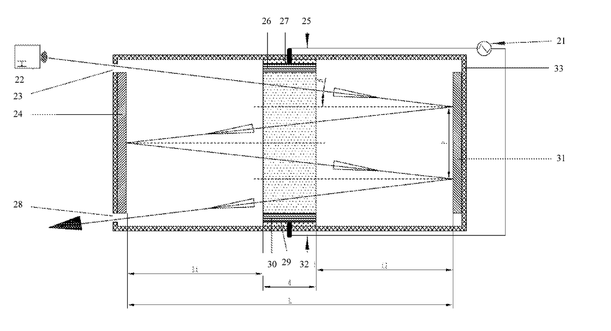
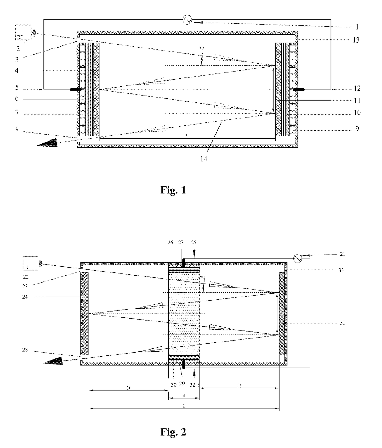
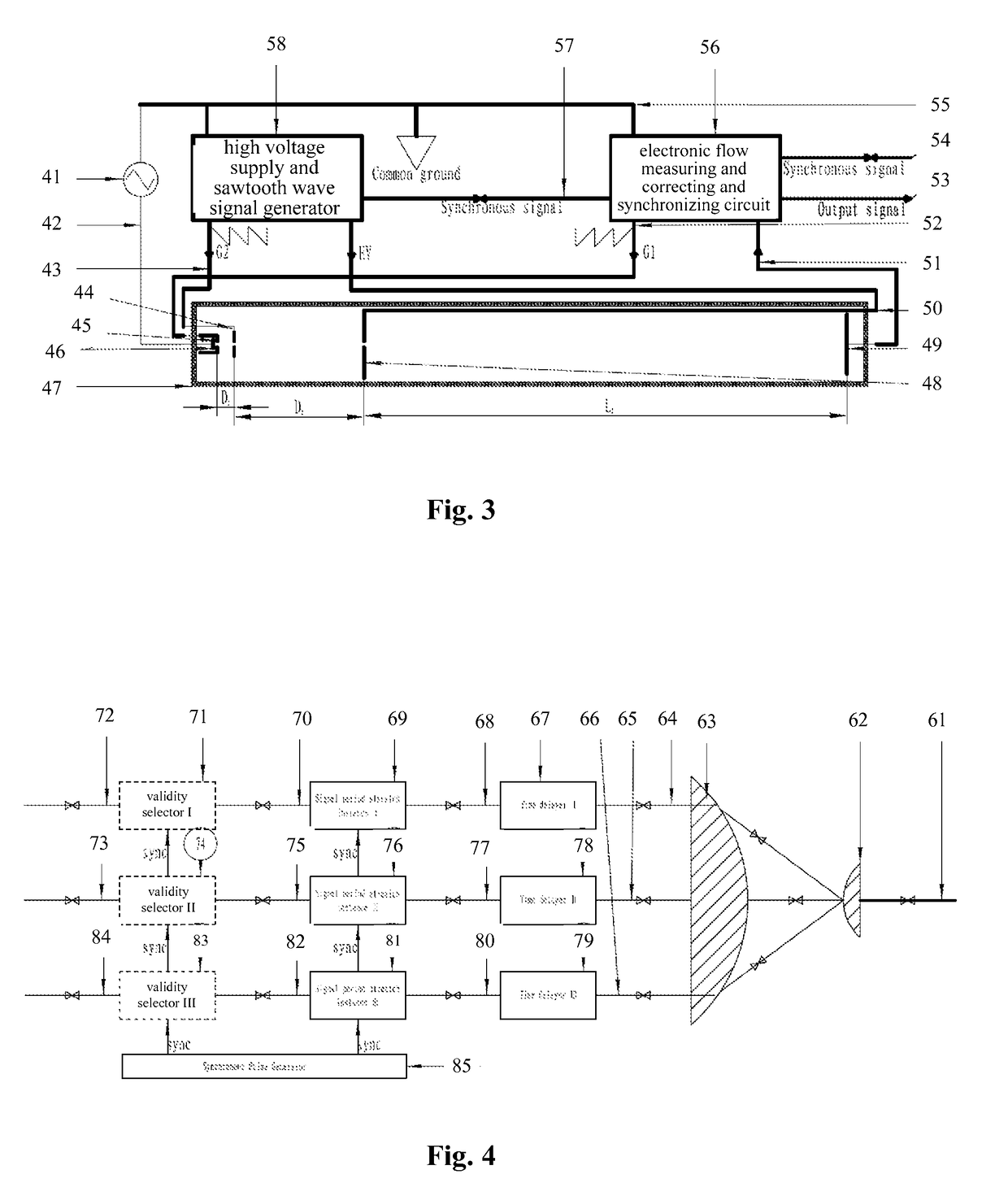
[0075]Referring to FIG. 1, a control signal generator 1 generates a movement control signal, so as to output a control signal which moves a left reflective panel 4 or right reflective panel 11 for a preset displacement when a target signal reaches the surface of the reflective panel. When the period of the target signal needs to be expanded, the control signal generator 1 outputs a control signal which moves the left reflective panel 4 or the right reflective panel 11 for the displacement in the same propagation direction as the target signal. When the period of the target signal needs to be shrunk, the control signal generator 1 outputs the control signal which moves the left reflective panel 4 or the right reflective panel 11 for the displacement in the opposite propagation direction relative to the target signal. The strong-weak change gradient of the control signal outputted from the control...


PUM


Abstract

Disclosed are a method and a device for signal period stretch and ultra-fast serial-to-parallel / parallel-to-serial conversion, which relate to the technical field of analysis and measurement control. The method is to change a propagation velocity of a target signal or displacement-reflecting the target signal, so as to extend or compress the period of the signal. Displacement-reflection is to generate a Doppler shift through interaction of the displacement of a reflecting plate with the target signal, so as to achieve period stretch; for a signal transmitted through a medium, the propagation velocity of the target signal is changed by changing the property of the medium, so as to achieve period stretch; for a signal ascribed to an electron flow, the movement velocity of the electron beam is changed through a varying acceleration field, so as to achieve period stretch. A target signal condensing / diffusing and collimating lens, a synchronous signal controller and a plurality of period stretch devices are utilized to achieve ultra-fast serial-to-parallel / parallel-to-serial signal conversion. Thereby, a device that originally cannot work at the frequency spectrum of the target signal is enabled to observe, transmit and parse content of the original target signal.

Description

FIELD OF THE INVENTION[0001]The invention relates to the field of analysis and measurement control technology, and more particularly to fast signal processing method (Time stretch), and also relates to high-speed data transmission in communications engineering field, and optical and nuclear engineering.BACKGROUND OF THE INVENTION[0002]In daily life or scientific and technological research, we often need to speed up the slow changing process, so that we can quickly understand all the process in general, or we need to slow down the fast changing process, so that we can find out any specific changes in detail in the changing process, which is called time stretch. Based on the application of the time stretch, there is a fast sampling technique based on a narrow pulse control signal which is usually used to rapid physical field of research, such as blasting, nuclear electronics, elementary particle movement characteristics, as well as a photoelectric signal sampling oscilloscope. However...

Claims


Application Information

Patent Timeline
Patent Type & Authority Patents(United States)
IPC IPC(8): G06F19/00G01S7/48H03M9/00G16Z99/00
CPCG06F19/00H03M9/00G01S7/48G16Z99/00
Inventor DONG, SHI
Owner CHONGQING MISEN TECH LTD
Learn More