Feedback circuit

Active Publication Date: 2018-07-31
MEANWELL GUANGZHOU ELECTRONICS
View PDF8 Cites 16 Cited by
  • Summary
  • Abstract
  • Description
  • Claims
  • Application Information

AI Technical Summary

Benefits of technology

[0008]Differing from conventional feedback controlling circuit can only make a LED driver circuit provide a constant output current and/or a constant output current, the primary objective of the present invention is to provide a novel feedback circuit, which can not only activate a PWM controlling unit to stabilize the output current and the output voltage of the LED driver circuit, but also can facilitate the LED driver circuit provide a constant output power. This feedback circuit comprises: a signal sampling unit, a feedback unit, a signal concerting unit, and a signal adjusting unit. During the operation of the feedback

Problems solved by technology

However, owing to linear power supply devices possessing many disadvantages such as large volume and poor power conversion rate, switch mode power supply (SMPS) device is invented by Neti R. M. Rao and disclosed in U.S. Pat. No. 4,253,137.
However, owing to the feedback unit 16′ and the PWM controlling unit 17′ can only singly reduce the output current

Method used


Image

  • Feedback circuit
  • Feedback circuit
  • Feedback circuit

Examples


Example

First Embodiment

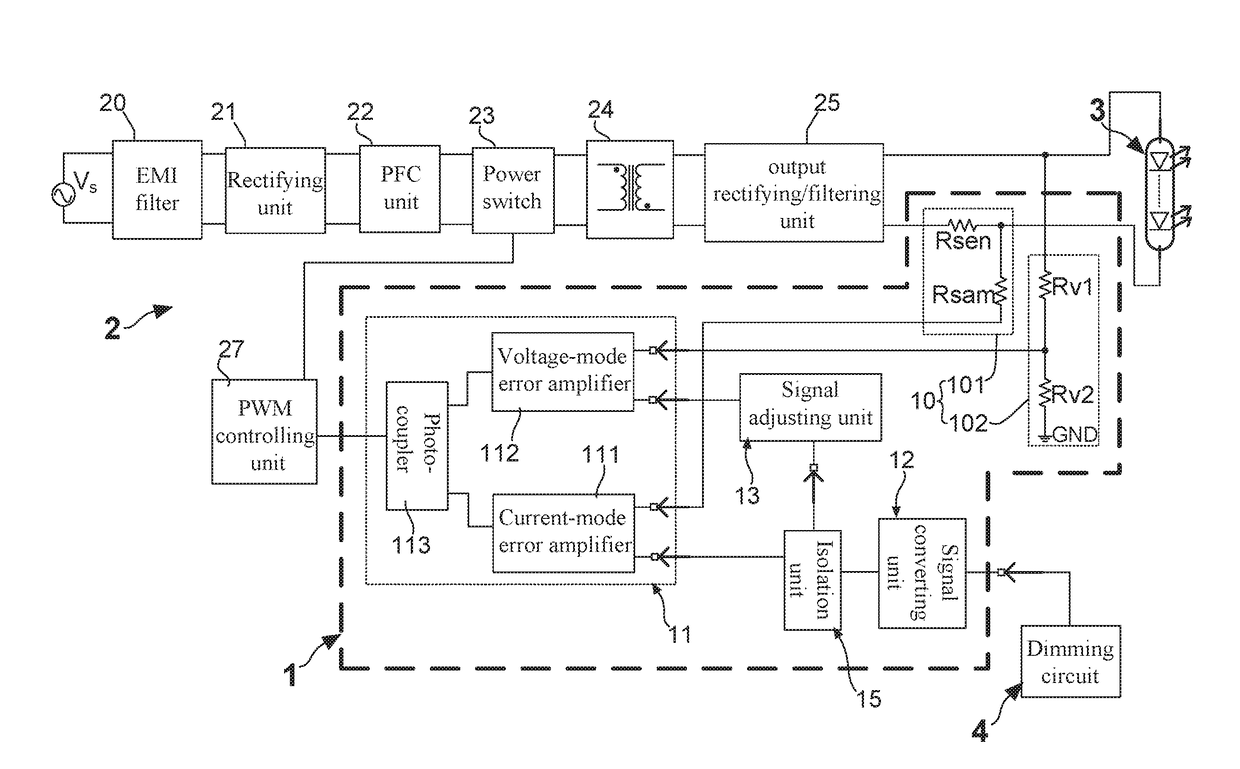
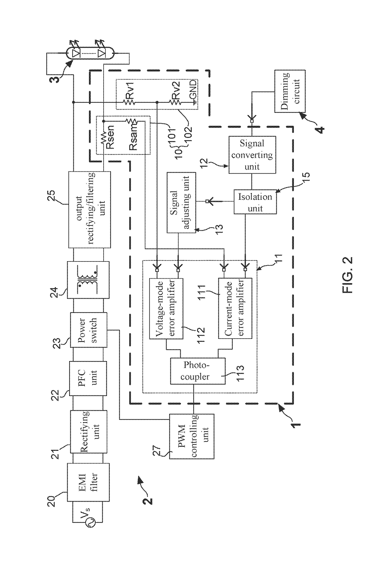
[0031]With reference to FIG. 2, there is provided a circuit block diagram of an LED power supply device having a feedback circuit of the present invention. As FIG. 2 shows, the LED power supply device 2 comprises: an electromagnetic interference (EMI) filtering unit 20 coupling to a voltage source VS, a rectifying unit 21, a power factor correction (PFC) unit 22, a power switch 23, a transformer unit 24, an output rectifying / filtering unit 25, and a pulse width modulation (PWM) controlling unit 27.

[0032]The feedback circuit 1 of the present invention is mainly used in the LED power supply device 2 for cooperating with the PWM control unit 27 so as to stabilize the output current, the output voltage and the output power of the LED power supply device 2. Briefly speaking, this feedback circuit 1 is particularly designed to provide an assistance on facilitating the LED power supply device 2 provide constant current and / or constant voltage to an LED lighting device 3 und...

Example

Second Embodiment

[0042]Continuously referring to FIG. 5 and FIG. 6, wherein FIG. 5 illustrates a circuit framework view of a second embodiment of the feedback circuit, and FIG. 6 shows a circuit block diagram of the LED power supply device having the feedback circuit of the present invention. After comparing FIG. 5 with FIG. 3, it can find that the second embodiment of the feedback circuit 1 comprises: a signal sampling unit 10, a feedback unit 11, a signal converting unit 12, and a signal adjusting unit 13. Moreover, differing from the signal adjusting unit 13 of the first embodiment is constituted by a differential amplifier 131, a voltage regulating unit 133 and a voltage comparator 132, the signal adjusting unit 13 of the second embodiment is an error detection unit.

[0043]From FIG. 5 and FIG. 6, it is able to know that, the signal adjusting unit 13 comprises: an operational amplifier OP′, a third voltage dividing resistor Rv3, a fourth voltage dividing resistor Rv4, a first diod...


PUM


Abstract

The present invention particularly discloses a novel feedback circuit, mainly comprising: a signal sampling unit, a feedback unit, a signal concerting unit, and a signal adjusting unit. During the operation of the feedback circuit, a current-mode error amplifier unit is configured to output a current error signal based on a current sampling signal and a dimming signal outputted by the signal converting unit, so as to activate a PWM controlling unit to stabilize an output current of a LED driver circuit. In the meantime, a voltage-mode error amplifier unit cooperates with the PWM controlling unit to adaptively regulate an output voltage of the LED driver circuit based on a voltage sampling signal and an adjustment signal outputted by the signal adjusting unit, in order to facilitate the LED driver circuit provides a constant output power.

Description

BACKGROUND OF THE INVENTION1. Field of the Invention[0001]The present invention relates to the technology field of electronic circuits, and more particularly to a feedback circuit applied in power converters and power supply devices.2. Description of the Prior Art[0002]With the continuous advance of electronic sciences and technologies, various electronic devices and products have been development and widely applied in human life. Traditionally, linear power supply devices are adopted for outputting voltage or current to power corresponding electronic devices. However, owing to linear power supply devices possessing many disadvantages such as large volume and poor power conversion rate, switch mode power supply (SMPS) device is invented by Neti R. M. Rao and disclosed in U.S. Pat. No. 4,253,137.[0003]SMPS technology is also applied for designing and manufacturing LED driver circuits. Please refer to FIG. 1, there is provided a circuit block diagram of a conventional LED driver circu...

Claims


Application Information

Patent Timeline
IPC IPC(8): H05B37/02H05B33/08H05B44/00
CPCH05B33/0887H05B33/0842H05B33/0815H05B33/0851H05B33/0845H05B45/10H05B45/36H05B45/325H05B45/355H05B45/14
Inventor LI, NANYANG, JIAN-DONG
Owner MEANWELL GUANGZHOU ELECTRONICS
Why Eureka
Try Eureka