In-situ temperature control during chemical mechanical polishing with a condensed gas

a technology of condensed gas and polishing process, which is applied in the direction of manufacturing tools, abrasive surface conditioning devices, lapping machines, etc., can solve the problems of poor topography and within die planarization, and increase the temperature of the substrate during the polishing process

Active Publication Date: 2018-08-28
APPLIED MATERIALS INC
View PDF20 Cites 2 Cited by
  • Summary
  • Abstract
  • Description
  • Claims
  • Application Information

AI Technical Summary

Problems solved by technology

Because the polishing pad is generally constructed of a polymer with poor thermal conductivity and the substrate is forced against the polishing pad by a polymer membrane in the carrier assembly, the heat generated increases the temperature of the substrate during the polishing process.
High and unstable temperatures can lead to removal rate variations over time and across the wafer, which will affect the ability to control the final thickness of the material at the end of the process.
In addition, for many CMP processes, higher temperatures will degrade the planarization efficiency, selectivity, or both leading to poor topography and within die planarization.
However, the insulating nature of the polishing pad positioned between the substrate and the platen reduce the effectiveness of this approach.
Removal of water from the polishing slurry is often difficult and expensive and runs the risk of drying the pad, leading to substrate defect issues.

Method used


Image

  • In-situ temperature control during chemical mechanical polishing with a condensed gas
  • In-situ temperature control during chemical mechanical polishing with a condensed gas
  • In-situ temperature control during chemical mechanical polishing with a condensed gas

Examples


Embodiment Construction

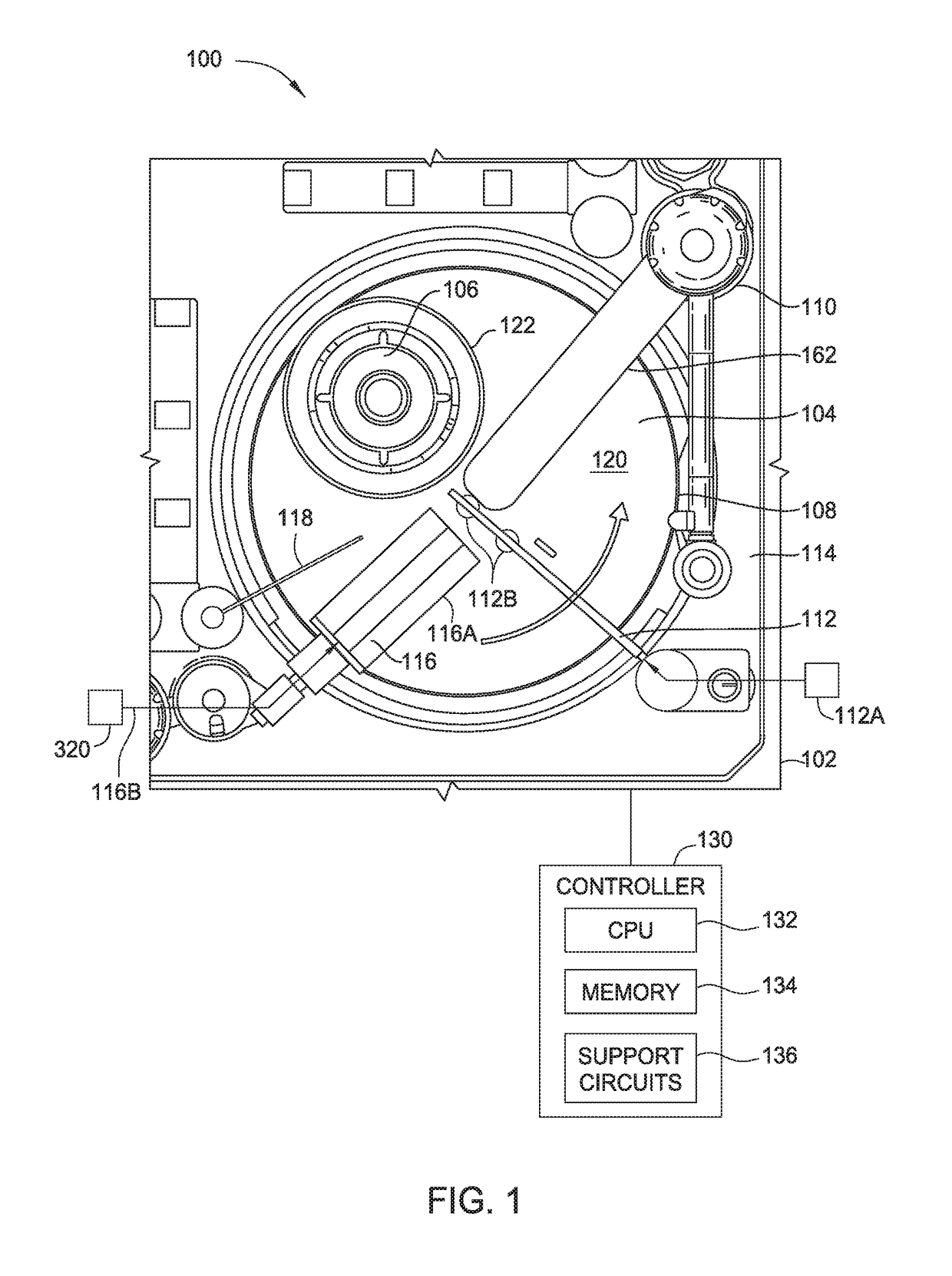
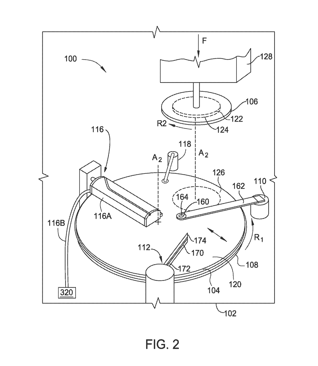
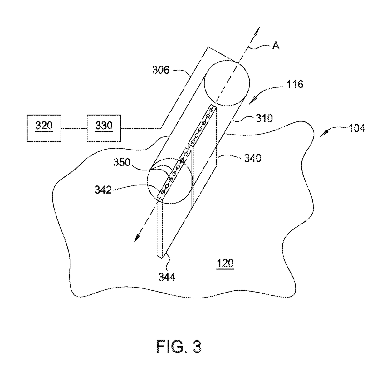
[0018]Implementations of the present disclosure generally relate to planarization of surfaces on substrates and on layers formed on substrates, including an apparatus for in-situ temperature control during polishing, and methods of using the same. More specifically, implementations of the present disclosure relate to in-situ temperature control with a condensed gas during a chemical-mechanical polishing (CMP) process. Certain details are set forth in the following description and in FIGS. 1-4 to provide a thorough understanding of various implementations of the disclosure. Other details describing well-known structures and systems often associated with substrate polishing and temperature control using condensed gases are not set forth in the following disclosure to avoid unnecessarily obscuring the description of the various implementations.

[0019]Many of the details, dimensions, angles and other features shown in the Figures are merely illustrative of particular implementations. Acc...


PUM

PropertyMeasurementUnit
temperatureaaaaaaaaaa

Abstract

Implementations of the present disclosure generally relate to planarization of surfaces on substrates and on layers formed on substrates, including an apparatus for in-situ temperature control during polishing, and methods of using the same. More specifically, implementations of the present disclosure relate to in-situ temperature control with a condensed gas during a chemical-mechanical polishing (CMP) process. In one implementation, the method comprises polishing one or more substrates against a polishing surface in the presence of a polishing fluid during a polishing process to remove a portion of a material formed on the one or more substrates. A temperature of the polishing surface is monitored during the polishing process. Carbon dioxide snow is delivered to the polishing surface in response to the monitored temperature to maintain the temperature of the polishing surface at a target value during the polishing process.

Description

CROSS-REFERENCE TO RELATED APPLICATIONS[0001]This application claims benefit of U.S. Provisional Patent Application Ser. No. 62 / 294,420, filed Feb. 12, 2016, which is incorporated herein by reference in its entirety.BACKGROUND[0002]Field[0003]Implementations of the present disclosure generally relate to planarization of surfaces on substrates and on layers formed on substrates, including an apparatus for in-situ temperature control during polishing, and methods of using the same. More specifically, implementations of the present disclosure relate to in-situ temperature control with a condensed gas during a chemical-mechanical polishing (CMP) process.[0004]Description of the Related Art[0005]In the fabrication of integrated circuits and other electronic devices, multiple layers of conducting, semiconducting, and dielectric materials are deposited on or removed from a surface of a substrate. The substrate may be a semiconductor substrate or a glass substrate. As layers of material are...

Claims


Application Information

Patent Timeline
Patent Type & Authority Patents(United States)
IPC IPC(8): B24B37/015B24B49/14B24B55/02B24B37/34B24C1/00
CPCB24B37/015B24B37/34B24B49/14B24B55/02B24C1/003B24B37/107B24B53/017
Inventor BROWN, BRIAN J.
Owner APPLIED MATERIALS INC
Why Eureka
Try Eureka