Method of detecting plasma discharge in a plasma processing system

a plasma processing system and plasma technology, applied in the direction of resistance/reactance/impedence, electric discharge tubes, instruments, etc., can solve the problems of plasma discharge detection, inability to distinguish between different types of light and plasma discharge, and inability to form a population of charged species and chemical reactive species necessary for performing the function of the plasma processing system, etc., to prevent damage to substrates and chamber components.

Active Publication Date: 2018-08-28
TOKYO ELECTRON LTD
View PDF5 Cites 14 Cited by
  • Summary
  • Abstract
  • Description
  • Claims
  • Application Information

AI Technical Summary

Benefits of technology

[0004]The formation of a population of charged species (ions, etc.) and chemically reactive species necessary for performing the function of the plasma processing system (i.e. material etch, material deposition, etc.) at the substrate surface, or for cleaning the plasma processing chamber of residues is not always perfectly maintained. The plasma itself can become extinguished during a given substrate processing or chamber cleaning operation. Detecting whether a plasma is being maintained or whether a plasma has been extinguished is beneficial to prevent damage to substrates and chamber components.
[0005]Conventionally, photodiode light sensors are widely used for plasma detection. In general, photodiode light sensors are robust, simple and inexpensive in manufacturing. Such sensors, however, can incorrectly detect existence of plasma. These sensors have a simple light detection function (“light on” or “light off”) and thus cannot distinguish between different types of light and plasma discharges. Being able to distinguish different plasma discharges can be very beneficial for some plasma reactors. For example, if a particular plasma is extinguished while plasma creation / maintenance power is still being coupled to a corresponding plasma chamber, then components of a plasma processing system can be damaged. Moreover, a given light sensor can still be able to detect light from a parasitic (abnormal) discharge in gas media, which prevents triggering alarms and / or keeps chamber operation continuous or otherwise keeps power coupled to the chamber, which can damage chamber components.

Problems solved by technology

The formation of a population of charged species (ions, etc.) and chemically reactive species necessary for performing the function of the plasma processing system (i.e. material etch, material deposition, etc.) at the substrate surface, or for cleaning the plasma processing chamber of residues is not always perfectly maintained.
Such sensors, however, can incorrectly detect existence of plasma.
These sensors have a simple light detection function (“light on” or “light off”) and thus cannot distinguish between different types of light and plasma discharges.
For example, if a particular plasma is extinguished while plasma creation / maintenance power is still being coupled to a corresponding plasma chamber, then components of a plasma processing system can be damaged.

Method used


Image

  • Method of detecting plasma discharge in a plasma processing system
  • Method of detecting plasma discharge in a plasma processing system
  • Method of detecting plasma discharge in a plasma processing system

Examples


Embodiment Construction

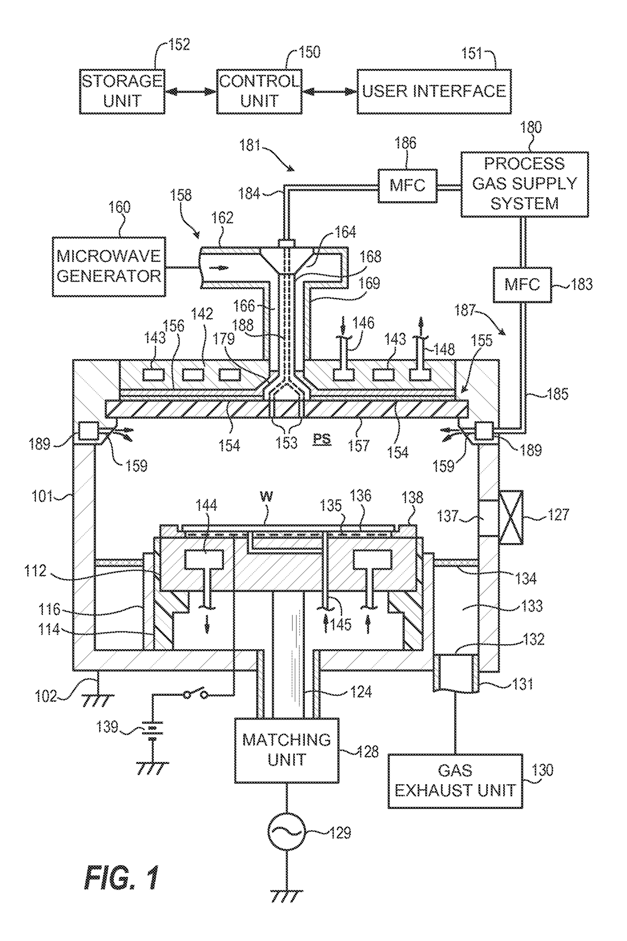
[0018]Techniques herein include applying a modulated low-power signal (“probe signal”) to an electrostatic chuck (ESC) from a bias power generator. A peak-to-peak (Vpp) voltage signal response or radio frequency (RF) current response is then monitored. The presence or absence of bulk plasma will result in different Vpp or RF current values, which indicate whether a plasma is detected.

[0019]Conventionally, various techniques have been implemented for exciting a gas into plasma for the treatment of a substrate during semiconductor device fabrication, as described above. In particular, (“parallel plate”) capacitively coupled plasma (CCP) processing systems, or inductively coupled plasma (ICP) processing systems have been used for plasma excitation. Among other types of plasma sources, there are microwave plasma sources (including those utilizing electron-cyclotron resonance (ECR)), surface wave plasma (SWP) sources, and helicon plasma sources.

[0020]Some plasma reactors are known as sur...


PUM


Abstract

Detecting presence or absence of plasma is accomplished from probe signals. In one embodiment, a low-power modulated signal is applied to an electrostatic chuck from a bias power generator. A corresponding system then monitors peak-to-peak voltage (Vpp) signal responses or radio frequency current responses. The probe signal can be generated to have insufficient power to either ignite or sustain plasma discharge (or cause component damage). Thus, low-duty and / or low current pulsing signals to be used. Presence or absence of the bulk plasma will then result in different Vpp or radio frequency current values.

Description

CROSS REFERENCE TO RELATED APPLICATIONS[0001]The present application claims the benefit of U.S. Provisional Patent Application No. 62 / 181,537, filed on Jun. 18, 2015, entitled “Method of Detecting Plasma Discharge in a Plasma Processing System,” which is incorporated herein by reference in its entirety.BACKGROUND OF THE INVENTION[0002]This disclosure relates to plasma processing systems.[0003]The fabrication of integrated circuits (IC) in the semiconductor industry typically employs plasma to create and assist surface chemistry within a plasma reactor necessary to remove material from and deposit material to a substrate. In general, plasma is formed within the plasma reactor under vacuum conditions by heating electrons to energies sufficient to sustain ionizing collisions with a supplied process gas. Moreover, the heated electrons can have energy sufficient to sustain dissociative collisions and, therefore, a specific set of gases under predetermined conditions (e.g., chamber pressu...

Claims


Application Information

Patent Timeline
Patent Type & Authority Patents(United States)
IPC IPC(8): H02J4/00G01R27/02H01J37/32
CPCH02J4/00G01R27/02H01J37/32935H01J37/32174H01J37/32183H01J37/32146
Inventor VORONIN, SERGEYRANJAN, ALOK
Owner TOKYO ELECTRON LTD
Why Eureka
Try Eureka