
Decoder and method at the decoder for synchronizing the rendering of contents received through different networks

a technology of content and decoding method, applied in the direction of selective content distribution, color television with bandwidth reduction, television system, etc., can solve the problems of not being able to synchronize the rendering of personalized components, all the frames of personalized components are useless, and the personalized components are received too late to be synchronized with the main component, so as to optimize the delay

Active Publication Date: 2018-08-28
INTERDIGITAL MADISON PATENT HLDG
View PDF30 Cites 1 Cited by
  • Summary
  • Abstract
  • Description
  • Claims
  • Application Information

AI Technical Summary

Benefits of technology

The invention aims to improve the synchronization of two components in a hybrid broadcast and broadband delivery system. It proposes a method that reduces the delay in accessing the on-demand component and minimizes the impact of bad time reference parameter estimation. The method allows for the frames of the broadband component to be delivered and presented at the same time as the broadcast component, ensuring that they are synchronized. This results in a better user experience and faster access to the on-demand component.

Problems solved by technology

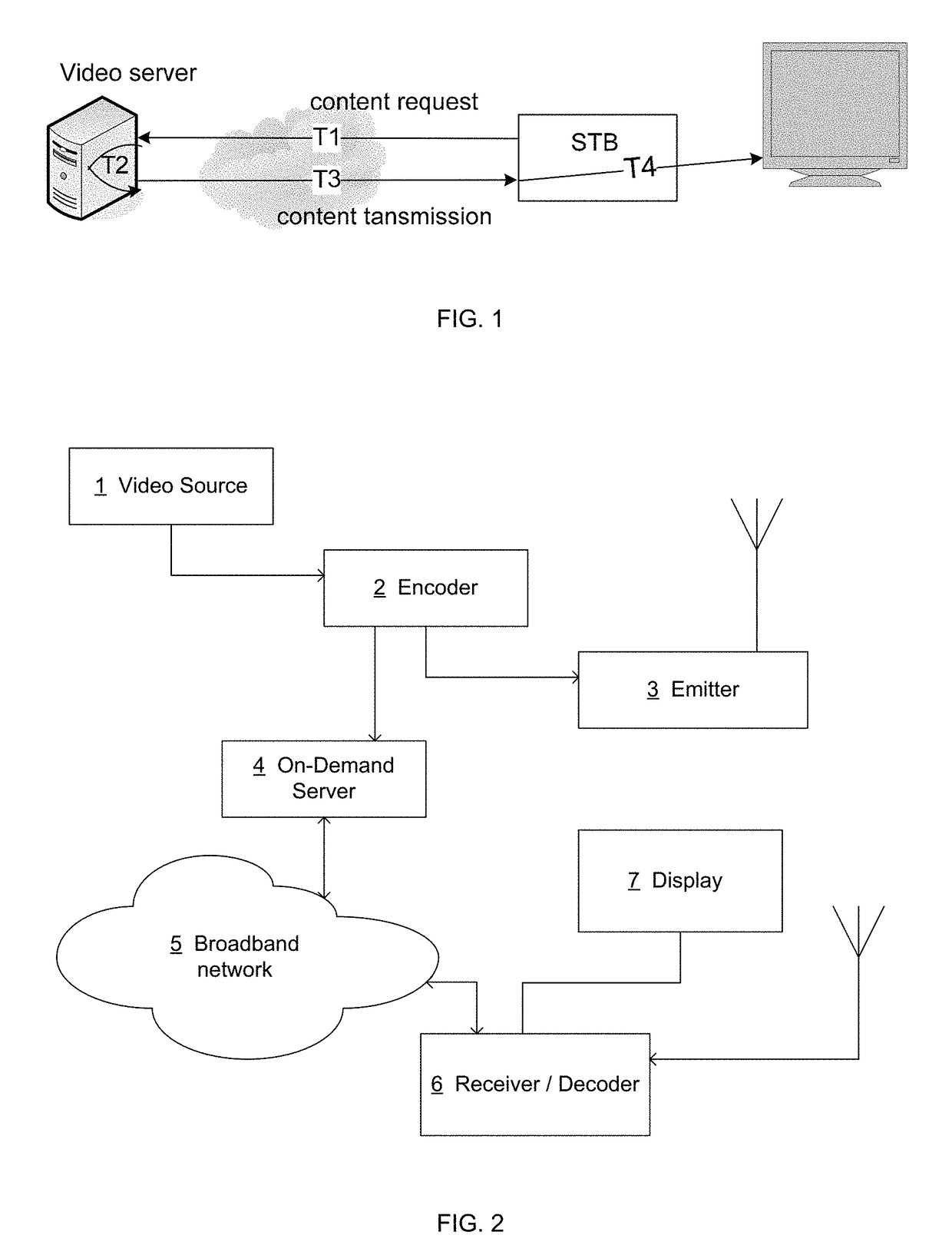
Either the personalized component stream can be received, decoded and presented before the corresponding frames of the main component are presented or it arrives after and in this case all the frames of the personalized component are useless.
In this case, and if the personalized component arrives later than the corresponding frames of the main component, it is not possible to synchronize their rendering.
If the offset is incorrectly evaluated, the personalized component is received too late to be synchronized with the main component.
A disadvantage of such a synchronization is that when a terminal requests for a personalized component to be synchronized with a main component and receives a content, starting with a key-frame, for which the decoding and presentation time reference indicate that the reception is too late to be synchronized with the main component, the discarded content may correspond to an important time range (up to many seconds) in term of rendering.

Method used


Image

  • Decoder and method at the decoder for synchronizing the rendering of contents received through different networks
  • Decoder and method at the decoder for synchronizing the rendering of contents received through different networks
  • Decoder and method at the decoder for synchronizing the rendering of contents received through different networks

Examples


first embodiment

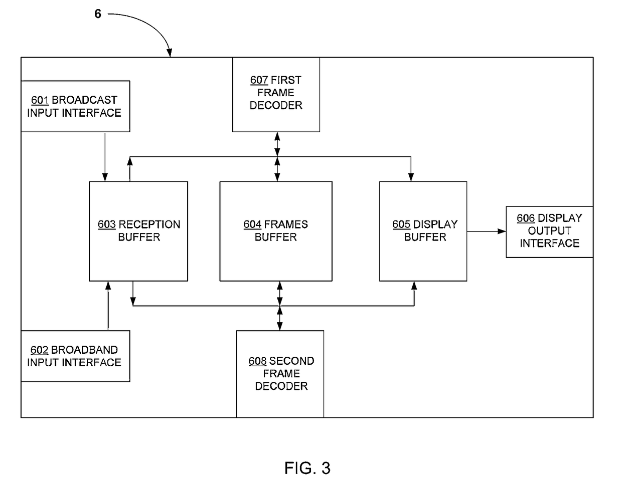
[0048]FIG. 2 illustrates a network architecture according to the invention. The broadcast timing is considered as a reference and the broadband network is adapted for the synchronization. A video source 1 delivers a non-encoded main component program to an encoder 2. The encoder 2 encodes the main component and transmits it to an emitter 3. The broadcasting of the main component by the emitter 3 could be done simultaneously with the encoding by the encoder 2 but also later. The main component is broadcasted over the air to a receiver / decoder 6. The encoder 2 also provides an encoded personalized component program to an on-demand server 4. The personalized component is synchronized with the main component. The encoder 2 can provide the personalized component during the encoding, but the personalized component can also be already available on the on-demand server 4. It can be available in a database of personalized component related to the main component to be broadcasted. The time re...

second embodiment

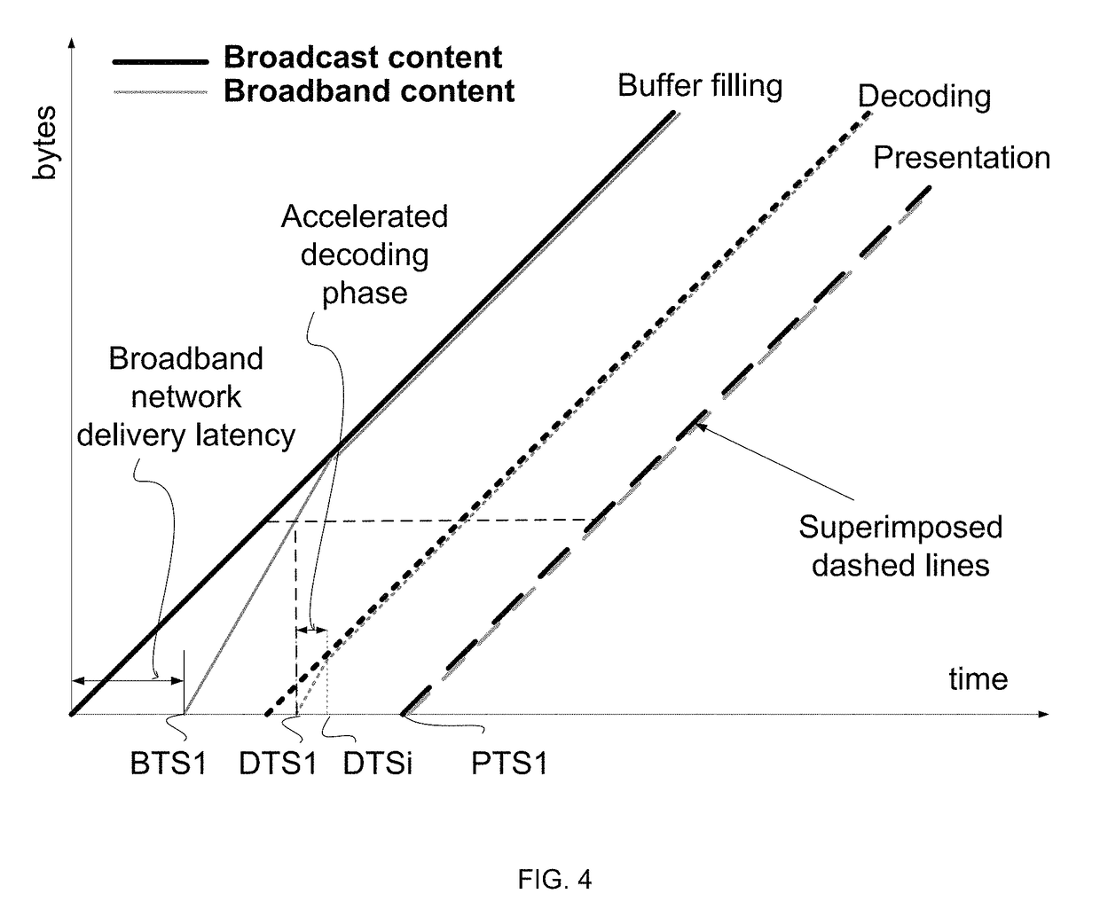
[0062]FIG. 7 illustrates a receiver / decoder 6 according to the invention. The personalized component (from broadband network) is composed of successive chunks containing many groups of pictures, the filtering module 609 filters the chunk content received at the broadband input interface 602 by reading some time reference information inside the chunk and / or in the group of pictures. The filter module 609 compares the time information within the received content with the program time references used by the receiver / decoder 6 for decoding and rendering. If the filter module detects that a chunk or a GOP is too late to synchronize the rendering of its content with the rendering of the received broadcast content, the GOP or chunk is not transmitted to the reception buffer. This avoids the second frame decoder 608 to decode a content present in the reception buffer 603 that can't be synchronized with the broadcast content. This filtering makes the rendering of both components possible ear...

third embodiment

[0063]According to the invention, the personalized component received over the bidirectional broadband network is an audio content comprising successive blocks of audio samples. Each of the blocks of audio samples comprising a time reference information for its decoding and rendering. The filtering module of the receiver / decoder filters parses the time information and transfers the blocks to the reception buffer only if the time reference information indicates that the samples can be decoded in time to be rendered in a synchronized way with the main component.

[0064]Obviously, the invention is not limited to main component and personalized component comprising video or audio carried as successive groups of pictures or chunks. The invention concerns all synchronized program contents comprising time reference information required for their decoding and presentation in a receiver that can be compared with the program clock reference (system clock).

[0065]References disclosed in the descr...


PUM


Abstract

A method of decoding an audio / video content transmitted over a broadband network. The method being based on the quick decoding of the first frames of a group of pictures without rendering them if the group of pictures arrives too late to be rendered synchronously with another audio / video content received through a broadcast network. The method allowing the synchronized rendering of contents respectively received over broadcast and broadband networks as soon as possible for the viewer.

Description

[0001]This application claims the benefit, under 35 U.S.C. §119 of EP Patent Application 11305271.6, filed 11 Mar. 2011.FIELD OF THE INVENTION[0002]The present invention relates generally to a method for decoding an audio video program received through a broadband network and more particularly to a method to synchronize the rendering of a content received through a broadband network with the rendering of a content received through a broadcast network.BACKGROUND OF THE INVENTION[0003]This section is intended to introduce the reader to various aspects of art, which may be related to various aspects of the present invention that are described and / or claimed below. This discussion is believed to be helpful in providing the reader with background information to facilitate a better understanding of the various aspects of the present invention. Accordingly, it should be understood that these statements are to be read in this light, and not as admissions of prior art.[0004]Over the past few...

Claims


Application Information

Patent Timeline
Patent Type & Authority Patents(United States)
IPC IPC(8): H04N7/12H04N21/81H04N21/235H04N21/8547H04N21/462H04N21/43H04N21/435
CPCH04N21/8126H04N21/235H04N21/435H04N21/8547H04N21/4622H04N21/814H04N21/8133H04N21/4307H04N21/43072H04N7/173
Inventor LAURENT, ANTHONYGAUTIER, ERICGILBERTON, PHILIPPE
Owner INTERDIGITAL MADISON PATENT HLDG
Learn More