Dither current power supply control method and dither current power supply control apparatus

a power supply control and current technology, applied in the direction of electric control, magnetic bodies, instruments, etc., can solve the problems of inability to follow current control, inability to carry out homogeneous dither control, and difficulty in calculating derivatives, so as to reduce the response dependency of feedback control and stable current control

Active Publication Date: 2018-09-18
MITSUBISHI ELECTRIC CORP
View PDF16 Cites 4 Cited by
  • Summary
  • Abstract
  • Description
  • Claims
  • Application Information

AI Technical Summary

Benefits of technology

[0020]The present invention has been made in view of the above-mentioned problems, and therefore has a first object to provide a dither current power supply control method for setting such an instruction current that a detected average current corresponding to a target average current is acquired even when a difference exists between a rise time and a fall time of a dither current, to thereby decrease a response dependency of feedback control on a fluctuating target current and carry out stable current control.
[0021]Moreover, a second object of the present invention is to provide a dither current power supply control apparatus for generating an instruction current with which a planned target average current is estimated to be acquired by using a correction parameter measured on an experimental stage, and superimposing a pulsating dither current on the instruction current, to thereby acquire a stable and highly precise energization current by using a simple calculation control circuit unit.
[0047]Thus, the negative feedback control is carried out by using the instruction current generated on the assumption that the planned target average current is acquired therewith, and hence there is an effect that the occurrence of a transient fluctuation error in automatic control is suppressed, and even when a control error is included in the detected average current corresponding to the instruction current due to other factors, the control error is automatically corrected by the negative feedback control, and highly precise energization control may be stably carried out.
[0049]Thus, the instruction current on the assumption that the planned target average current is acquired therewith is generated by using the correction parameter measured on the experimental stage. Consequently, there is an effect that the occurrence of a transient fluctuation error in automatic control is suppressed, and a stable and highly precise energization current may be acquired by using the simple calculation control circuit unit.

Problems solved by technology

Thus, in a case where such negative feedback control as to cause a target average current Iaa and a detected average current Idd to simply match each other is carried out without focusing on the dither medium current I0, consideration needs to be given to such a problem that homogeneous dither control cannot be carried out.
However, when the cycle of the sinusoidal wave is increased so that the current control may follow the sinusoidal wave, there is a problem in that a stationary state of the movable iron 14 occurs to generate the static friction resistance.
Moreover, when the cycle of the sinusoidal wave is decreased, there is a problem in that the current control cannot follow and the rise time and the fall time of the dither current do not match each other.
Moreover, it is difficult to calculate a derivative, which is a degree of a change in a deviation signal between a pulsating instruction current and a pulsating detected current, based on the deviation signal, and there is a problem in that precise derivative control cannot be expected.
However, when the cycle of the triangular wave is increased so that the current control may follow the triangular wave, there is a problem in that a stationary state of the spool 942 occurs to generate the static friction resistance.
Moreover, when the cycle of the triangular wave is decreased, there is a problem in that the current control cannot follow and the rise time and the fall time of the dither current do not match each other.

Method used


Image

  • Dither current power supply control method and dither current power supply control apparatus
  • Dither current power supply control method and dither current power supply control apparatus
  • Dither current power supply control method and dither current power supply control apparatus

Examples


first embodiment

(1) Detailed Description of Configuration

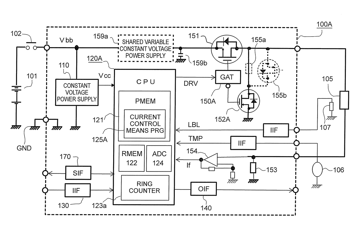
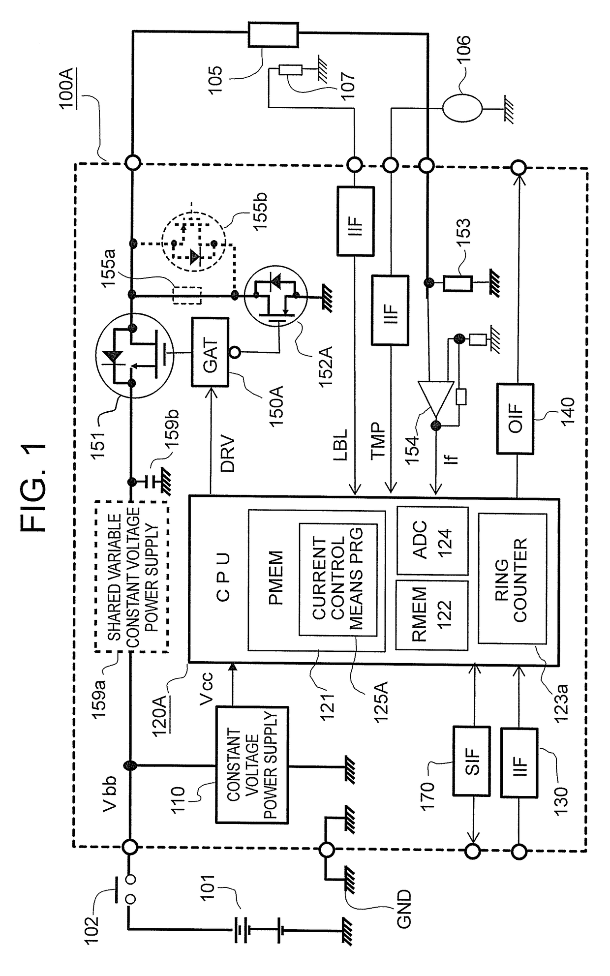
[0064]Now, a description is given of FIG. 1, which is an overall circuit block diagram for illustrating an apparatus according to a first embodiment of the present invention.

[0065]In FIG. 1, a dither current power supply control apparatus 100A supplies an excitation current including a dither current to a proportional solenoid coil 105 provided for each of a plurality of hydraulic solenoid valves for selecting a shift position in, for example, a transmission for a motor vehicle, and is configured to receive an application of a power supply voltage Vbb from an external power supply 101, which is an in-vehicle battery, via an output contact 102 of a power supply relay energized when a power supply switch (not shown) is closed.

[0066]Note that, a label resistor 107 for correcting an individual variation fluctuation in an excitation current-to-hydraulic pressure characteristic is provided for each of the plurality of proportional solenoid coils 10...

second embodiment

(1) Detailed Description of Configuration

[0186]Referring to FIG. 7, which is an overall circuit block diagram for illustrating an apparatus according to the second embodiment of the present invention, a detailed description is now given of a configuration of the apparatus with a focus on a difference from the apparatus of FIG. 1.

[0187]Note that, in respective drawings, like reference numerals denote like or corresponding components, a capital alphabet added as a suffix to each reference numeral represents a difference between the embodiments.

[0188]As a main difference between FIG. 1 and FIG. 7, the commutation circuit device 152A, which is the field effect transistor, is changed to a commutation circuit device 152B, which is a diode, and a difference also exists in the high speed shutoff circuit. Further, in place of the temperature sensor 106, a resistance detection circuit 180 is used, and the label resistor 107 is not shown.

[0189]In FIG. 7, to a dither current power supply contro...

third embodiment

(1) Detailed Description of Configuration

[0246]Referring to FIG. 11, which is an overall circuit block diagram for illustrating an apparatus according to the third embodiment of the present invention, a detailed description is now given of a configuration of the apparatus with a focus on a difference from the apparatus of FIG. 1.

[0247]Note that, in respective drawings, like reference numerals denote like or corresponding components, and a capital alphabet added as a suffix to each reference numeral represents a difference between the embodiments.

[0248]First, as a fundamental difference between FIG. 1 and FIG. 11, in FIG. 11, a negative feedback control circuit 160 is provided between a calculation control circuit unit 120C and a gate circuit 150C, and the negative feedback circuit 160 is configured to smooth the command pulse signal PLS generated by the calculation control circuit unit 120C, and apply switching control to the drive switching device 151 so that the energization curre...


PUM

PropertyMeasurementUnit
temperatureaaaaaaaaaa
sliding resistanceaaaaaaaaaa
energization currentaaaaaaaaaa

Abstract

In the dither current power supply control method, in order to prevent occurrence of a difference between the target average current and the detected average current, which is caused when a medium current (I0) between a dither large current (I2) and a dither small current (I1) and a waveform average (Ia) of the dither current are different from each other depending on a response time difference (a−b) between a rise time (b) and a fall time (a) of the dither current, negative feedback control is carried out by using a command medium current corresponding to the target average current corrected by a correction parameter based on experimentally measured data, thereby suppressing occurrence of a transient fluctuation error by the negative feedback control, so that a highly precise and stable load current is acquired.

Description

BACKGROUND OF THE INVENTION[0001]1. Field of the Invention[0002]The present invention relates to improvements in a dither current power supply control method and apparatus, for applying an increase / decrease current to an inductive electric load for driving a reversible positioning actuator, against a static friction resistance acting on a driven body.[0003]2. Description of the Related Art[0004]For example, in a transmission control apparatus, a suspension control apparatus, and the like for a motor vehicle, a proportional solenoid valve for controlling a hydraulic cylinder, which is an actuator, is used. In order to control a position of a movable valve of the proportional solenoid valve, a dither current is supplied to a proportional solenoid coil, which is an inductive electric load. The proportional solenoid coil generates, against a static friction resistance acting on the movable valve and a spring force pressing the movable valve in one direction, a pressing force in the othe...

Claims


Application Information

Patent Timeline
Patent Type & Authority Patents(United States)
IPC IPC(8): H01H47/00H01F7/06F02D41/14H01F7/18
CPCH01F7/064H01F7/1844F02D41/1408H01F2007/1866F16K31/06G05F1/40H02M7/21
Inventor MATSUMOTO, SHUICHINAKANISHI, MASATOIGUCHI, SHINGOARITA, HIROYUKIOGATA, TOMOAKI
Owner MITSUBISHI ELECTRIC CORP
Why Eureka
Try Eureka