
System and method for measuring a magnetic gradient field

a gradient field and magnetic field technology, applied in the field of magnetic field imaging, can solve the problems of not carrying useful gradient signal information, noise cancellation of near perfect common mode magnetic field, and low signal-to-noise ratio, so as to improve the signal-to-noise ratio, improve the efficiency of detecting microwave signals, and improve the effect of signal-to-noise ratio

Active Publication Date: 2018-10-02
QUSPIN
View PDF23 Cites 43 Cited by
  • Summary
  • Abstract
  • Description
  • Claims
  • Application Information

AI Technical Summary

Benefits of technology

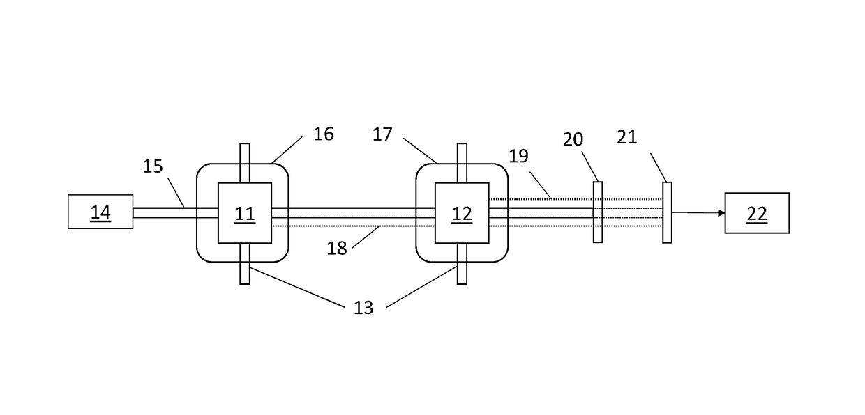
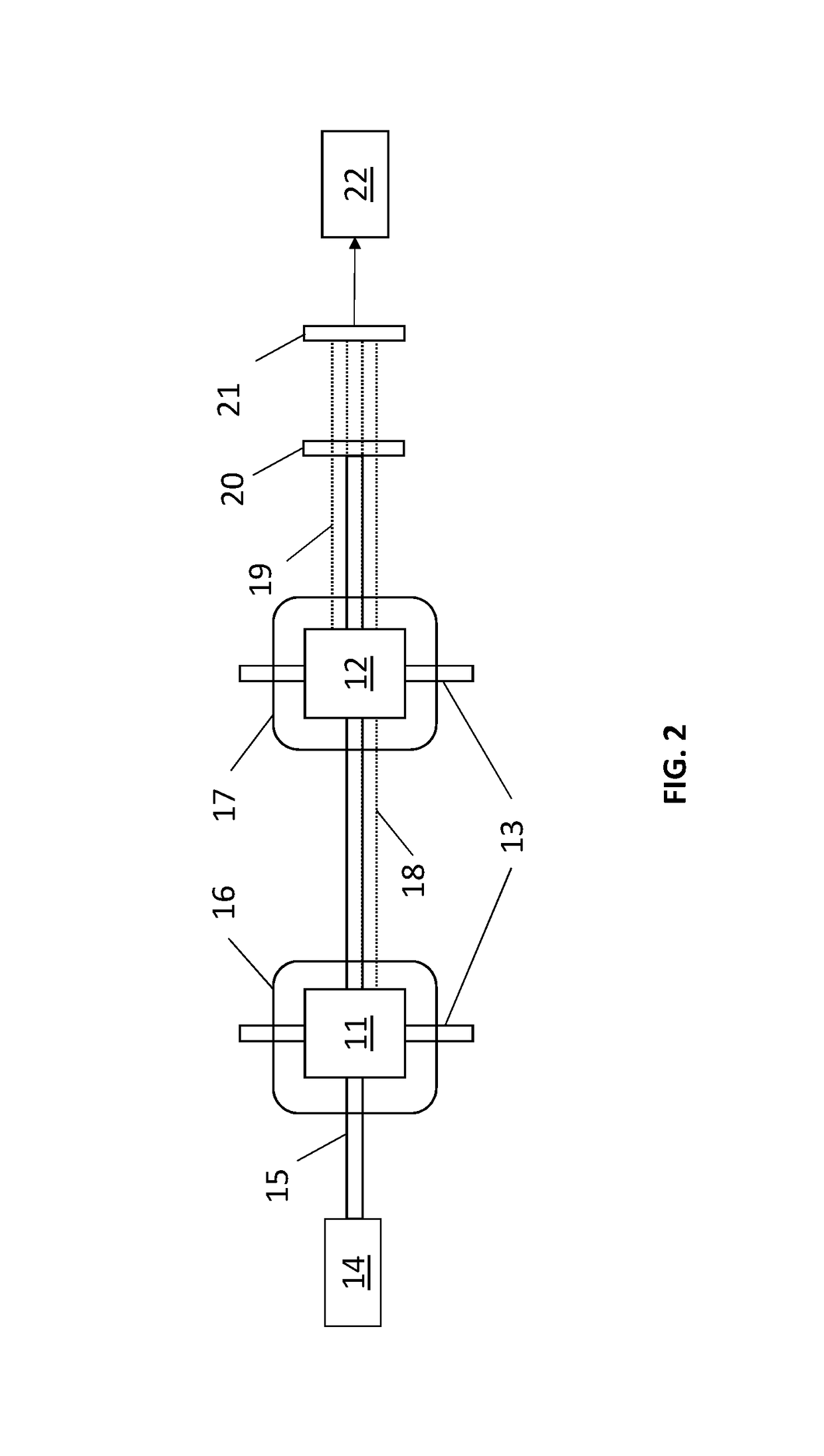
The current invention is a new device that allows for direct detection of the beat note, which is a crucial measure of magnetic field strength. This is done by using optical detection instead of a microwave cavity, which increases the efficiency of detecting the microwave signals. The device also removes residual carrier probe light that does not contribute to the signal, which improves the signal-to-noise ratio. This invention can be used as a hyperfine magnetometer or a gradiometer, without using a microwave cavity.

Problems solved by technology

The ability to measure gradient field directly without measuring the magnetic field leads to near perfect common mode magnetic field noise cancellation.
In addition to providing direct detection of the beat note, the current invention allows for removal of the residual carrier probe light that has not interacted with the atoms, and therefore does not carry any useful gradient signal information.
Removing the residual probe light can greatly improve signal-to-noise ratio which is one of the main problems that has plagued hyperfine magnetometers / gradiometers in prior art.

Method used


Image

  • System and method for measuring a magnetic gradient field
  • System and method for measuring a magnetic gradient field
  • System and method for measuring a magnetic gradient field

Examples


example

[0023]As an example, a magnetic gradiometer based on microwave sideband generation has been constructed out of two vapor cells 30 and 31 as shown in FIG. 5. A laser with 32 is used to generate the light beam 33 used for pumping and probing. The light beam was circularly polarized with a quarter-wave plate 34 and the wavelength of the light beam 33 is tuned near the |5S1 / 2, F=2↔|5P1 / 2transition of 87Rb atoms 35 confined inside the vapor cells 30 and 31. The light 33 was used to populate the |5S1 / 2, F=2, mF=2state with high probability. A microwave □ / 2 pulse at t=tm is applied to the atoms 35 inside the two vapor cells 30 and 31 with antennas 36 and 37 placed in the vicinity of the cells 30 and 31. The microwave □ / 2 pulse was resonant with the |5S21 / 2, F=2, mF=2|5S1 / 2, F=1, mF=1transition at the respective atom locations. After the microwave pulse is applied, the atoms 35 in the two vapor cells 30 and 31 start to precess in a coherent superposition of the |5S1 / 2, F=2, mF=2↔|5S1 / 2, F=1...


PUM


Abstract

A system and method is described to measure the magnetic field gradient using an optically pumped magnetometer configured as an intrinsic gradiometer. Atoms are prepared in a freely precessing coherent superposition of the magnetically sensitive hyperfine ground states in two or more physically separated locations. A probe laser beam is used to interrogate atoms in both locations. As the probe light beam passes through the coherent atoms, optical sidebands are self-generated at the ground state hyperfine frequency of the magnetically sensitive states. Each of the two sets of atoms produces distinct sidebands at a frequency separation proportional to the magnetic field experienced by each set of atoms. The probe light is captured using a photodetector. The self-generated probe optical sidebands interfere to produce a beat note whose frequency is proportional to the magnetic field gradient between the two sets of atoms. Measuring the frequency of the beat note therefore provides an accurate reading of the magnetic field gradient. An optical filter or a polarizer can be additionally used to remove the central frequency of the probe light, thus removing the noise produced by the residual probe beam.

Description

[0001]The following application is an application for patent under 35 USC 111 (a). This invention was made with government support under contract number D16PC00195 awarded by the Defense Advanced Research Projects Agency (DARPA). The government has certain rights in the invention.FIELD OF INVENTION[0002]This disclosure relates to magnetic field imaging, specifically a system and method thereof.BACKGROUND[0003]Optically pumped magnetometers (OPMs), also called atomic magnetometers, optical magnetometers, or optical atomic magnetometers, operate by measuring the transition frequency between two magnetically sensitive ground states of atoms with unpaired electrons such as rubidium (Rb), cesium (Cs), and potassium (K) for example. For an overview, see Budker and Romalis (Budker and Romalis, 2010). When measuring the transition frequency between Zeeman levels of the same hyperfine ground state, the frequency is in the kHz range, and when measuring the transition frequency between Zeeman ...

Claims


Application Information

Patent Timeline
Patent Type & Authority Patents(United States)
IPC IPC(8): G01V3/00G01R33/032G01R33/12G01R33/26
CPCG01R33/26G01R33/032G01R33/1284
Inventor SHAH, VISHAL
Owner QUSPIN
Learn More