Exposure method, method of fabricating periodic microstructure, method of fabricating grid polarizing element and exposure apparatus
a technology of grid polarizing element and exposure apparatus, which is applied in the direction of microlithography exposure apparatus, polarising elements, instruments, etc., can solve the problems of two light beams interfering, and achieve the effect of reducing the number of shots, small size, and reducing the cos
- Summary
- Abstract
- Description
- Claims
- Application Information
AI Technical Summary
Benefits of technology
Problems solved by technology
Method used
Image
Examples
first embodiment
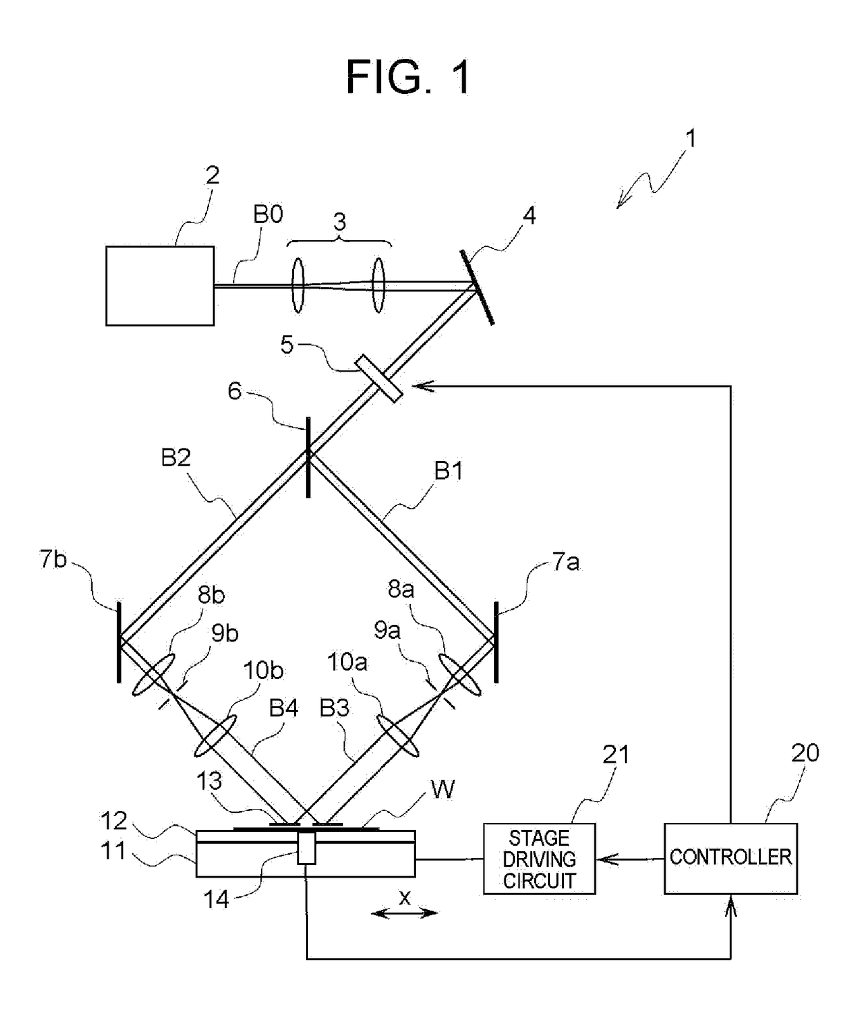
[0075]FIG. 1 is a view schematically showing an exemplary configuration of an exposure apparatus according to the present invention.
[0076]In FIG. 1, reference sign l denotes the exposure apparatus. The exposure apparatus is provided with a light source 2, a beam expander 3, a downwardly deflecting mirror 4; a shutter 5, a beam branching element 6, a reflecting (or folding) mirrors 7a and 7b, a light condensing (condenser) lenses 8a and 8b, pinholes 9a and 9b, and collimating lenses 10a and 10b. Furthermore, the exposure apparatus 1 may be provided with a stage 11, an adhesive disk 12, a mask 13, a gap sensor 14, a controller 20, and a stage driving circuit 21.
[0077]The light source 2 is a coherent light source which emits coherent light, and for example, a semiconductor excited (pumped) solid laser that emits the laser light having a wavelength λ of, for example, 266 nm. The beam diameter of the laser light B0, emitted from the light source 2, is expanded (enlarged) by the beam expa...
second embodiment
[0151]Hereinafter, a second embodiment of the present invention will be described below in detail.
[0152]In the above mentioned first embodiment, when the effective irradiation regions E0 are aligned with one another in the substrate conveying direction, the interfering regions E1 are not overlapped each other but the non-interfering regions E2 are overlapped each other. On the other hand, according to the second embodiment, the non-interfering region E2 is overlapped with the neighboring interfering region E1.
[0153]FIG. 14 is a view showing an exposure method according to the second embodiment.
[0154]As shown in FIG. 14A, the exposure apparatus 1 conveys the work W so as not to overlap the interfering region E1 in the effective irradiation region E0 at m-th exposure and the interfering region E1 in the effective irradiation region E0 at (m−1)-th exposure. Furthermore, according to the second embodiment, the exposure apparatus 1 conveys the work W so as to overlap the interfering regi...
third embodiment
[0159]Next, hereinafter, a third embodiment of the present invention will be described below in detail.
[0160]In the above mentioned first and second embodiments, the mask 13 is arranged above the workpiece W with the gap D being provided. On the other hand, according to the third embodiment, the mask 13 is arranged directly on the workpiece W without the gap D being provided.
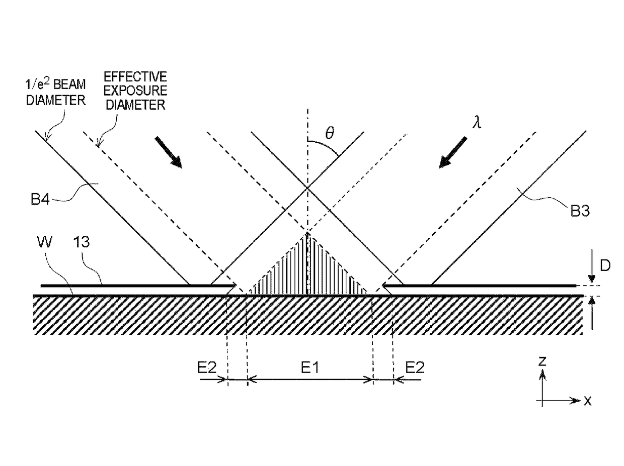
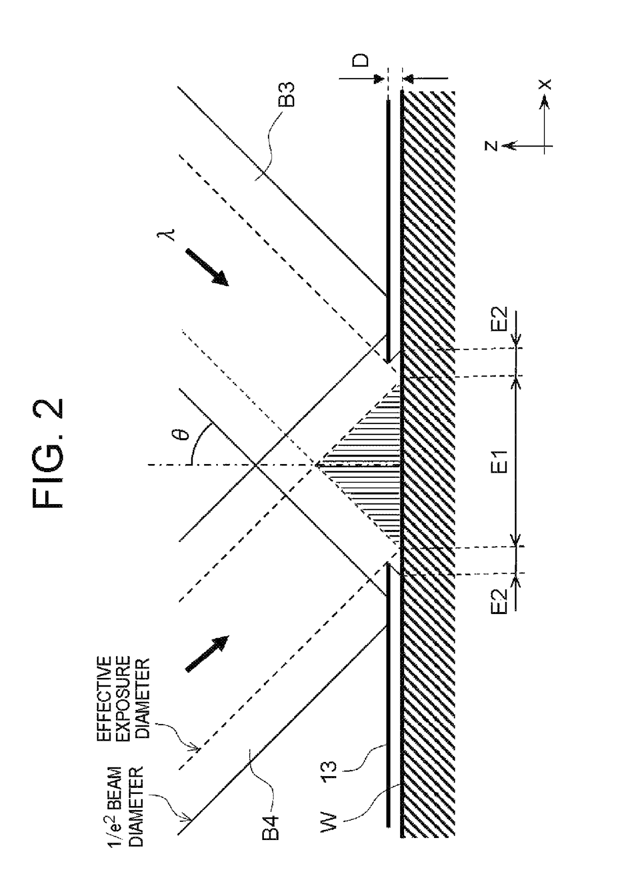
[0161]In the third embodiment, the exposure apparatus 1 performs the exposure in a state that the mask 13 is contacting the workpiece W. In this case, as the light beam is not wrapped around unlike those shown in FIG. 2, the non-interfering region E2 is not formed at both edges of the interfering region E1. In other words, the area of the effective irradiation region E0 is become equal to the area of the interfering region E1.
[0162]When exposing by the step-and-repeat method, as shown in FIG. 15, the exposure is to be performed so as not to overlap the neighboring interfering regions E1 (=the effective irradiati...
PUM
| Property | Measurement | Unit |
|---|---|---|
| wavelength | aaaaa | aaaaa |
| size | aaaaa | aaaaa |
| photosensitive threshold | aaaaa | aaaaa |
Abstract
Description
Claims
Application Information
 - R&D
- Intellectual Property
- Life Sciences
- Materials
- Tech Scout
- Unparalleled Data Quality
- Higher Quality Content
- 60% Fewer Hallucinations
Browse by: Latest US Patents, China's latest patents, Technical Efficacy Thesaurus, Application Domain, Technology Topic, Popular Technical Reports.
© 2025 PatSnap. All rights reserved.Legal|Privacy policy|Modern Slavery Act Transparency Statement|Sitemap|About US| Contact US: help@patsnap.com


