Methods, systems and apparatus for microfluidic crystallization based on gradient mixing

a microfluidic crystallization and gradient mixing technology, applied in the field of methods, systems and apparatus for microfluidic crystallization based on gradient mixing, can solve problems such as difficult retrieval of protein samples, and achieve the effects of convenient establishment of hundreds of unique concentrations, high throughput, and convenient study

Active Publication Date: 2019-01-01
ARIZONA STATE UNIVERSITY
View PDF14 Cites 8 Cited by
  • Summary
  • Abstract
  • Description
  • Claims
  • Application Information

AI Technical Summary

Benefits of technology

[0004]The present invention provides apparatus, systems and methods for microfluidic crystallization based on gradient mixing are described herein. The invention may beneficially facilitate the study of several hundreds of individual solution combinations in a microfluidic nanowell array for crystal growth, as well as the characterization of the resulting crystals in these nanoliter wells. The microfluidic apparatus may permit parallel high throughput batch crystallization experiments in nanoliter wells arranged in arrays that allow analyte and precipitant solutions to mix, split and recombine as the wells are filled. The array design and integrated valves further permit filling and mixing of analyte solution and precipitant under laminar flow conditions initiated through suction or pressure pumping, for example. The array's arrangement of channels and nanowells, in conjunction with controlled flow rates, may beneficially facilitate the establishment of hundreds of unique concentrations in the plurality of nanowells. Once filled, the nanowells may be advantageously sealed via valves thereby allowing crystallization to occur therein in parallel with each other. Still further, filling of the nanowells may be accomplished using laminar flow that may permit straightforward estimation of concentrations of analyte and precipitant in the nanowell array. Ultimately, numerical simulations based on analyte and precipitant concentration, flow parameters and device geometry, for example, may allow phase diagrams to be constructed to identify nanocrystal growth.
[0005]In various embodiments, the microfluidic apparatus may advantageously minimize overall sample consumption and utilize as little as a few microliters of each analyte and precipitant solution for several hundred parallel experiments in the nanowells, rendering the apparatus beneficial for use with precious samples. Still further, filling and mixing of the analyte and precipitant in the nanowells may be accomplished by controlled vacuum suction or pressure pumping, for example, in less than a minute for rapid concentration gradient establishment. Furthermore, hundreds of experiments may be performed in the nanowells of a single apparatus for efficient crystallization screening. Once the nanowells have been filled with the analyte and precipitant solutions, the compartments may be isolated by elastomeric “doormat valve” sealing via a membrane, for example, that may reduce or eliminate interference from both adjacent wells and the environment in order to provide natural, undisturbed crystal growth. Combined, hundreds of trials may be setup rapidly using small sample volumes and conditions may be maintained for days or weeks to crystal growth.
[0006]Still further, the apparatus may be fabricated with transparent materials, thereby enabling post-crystal growth imaging within the apparatus using a variety of methods, including, but not limited to, fluorescence microscopy and second order nonlinear imaging of chiral crystals (“SONICC”). Since the mixed analyte and precipitant solutions within the apparatus may be sealed after filling of the wells, the solutions may advantageously remain unexposed to the external environment during imaging thereby avoiding contamination and evaporation issues. As noted above, after imaging, wells where crystals are detected can be located and corresponding analyte and precipitant concentrations may be assigned from the numerical simulations of the mixing phenomena (e.g., solution flow rates and initial concentrations, as well as apparatus geometry). These concentrations in the nanowells may then be plotted as phase diagrams for crystallization of examined analytes. In addition, the invention may permit direct upscaling of crystallization conditions for larger scale experiments in which high crystal throughput and amount are required.

Problems solved by technology

Typically, protein samples may be difficult to retrieve and the sample amount is a pivotal factor in crystallization studies, in particular for large protein complexes such as membrane proteins.

Method used


Image

  • Methods, systems and apparatus for microfluidic crystallization based on gradient mixing
  • Methods, systems and apparatus for microfluidic crystallization based on gradient mixing
  • Methods, systems and apparatus for microfluidic crystallization based on gradient mixing

Examples


Embodiment Construction

[0027]As used herein, with respect to measurements and numerical ranges, “about” means + / −5%.

[0028]As used herein, the term “analyte solution” may include any suitable particle or analyte including, but not limited to, proteins, such as membrane proteins such as photosystem I (PSI) and pigment protein complexes like photoactive yellow protein (PYP) and phycocyanin, as well as enzymes like lysozymes, and other substances such as nucleic acids, microparticles, nanoparticles, biological cells, viruses, biomolecules, nanocrystals, cancer cells, mitochondria or other cell organelles.

[0029]As used herein, the term “precipitant” may include solutions containing salts such as sodium chloride (NaCl), magnesium sulfate (MgSO4) and ammonium sulfate ((NH4)2SO4) or other constituents such as buffering agents, detergents, organic solvents or polymers, for example.

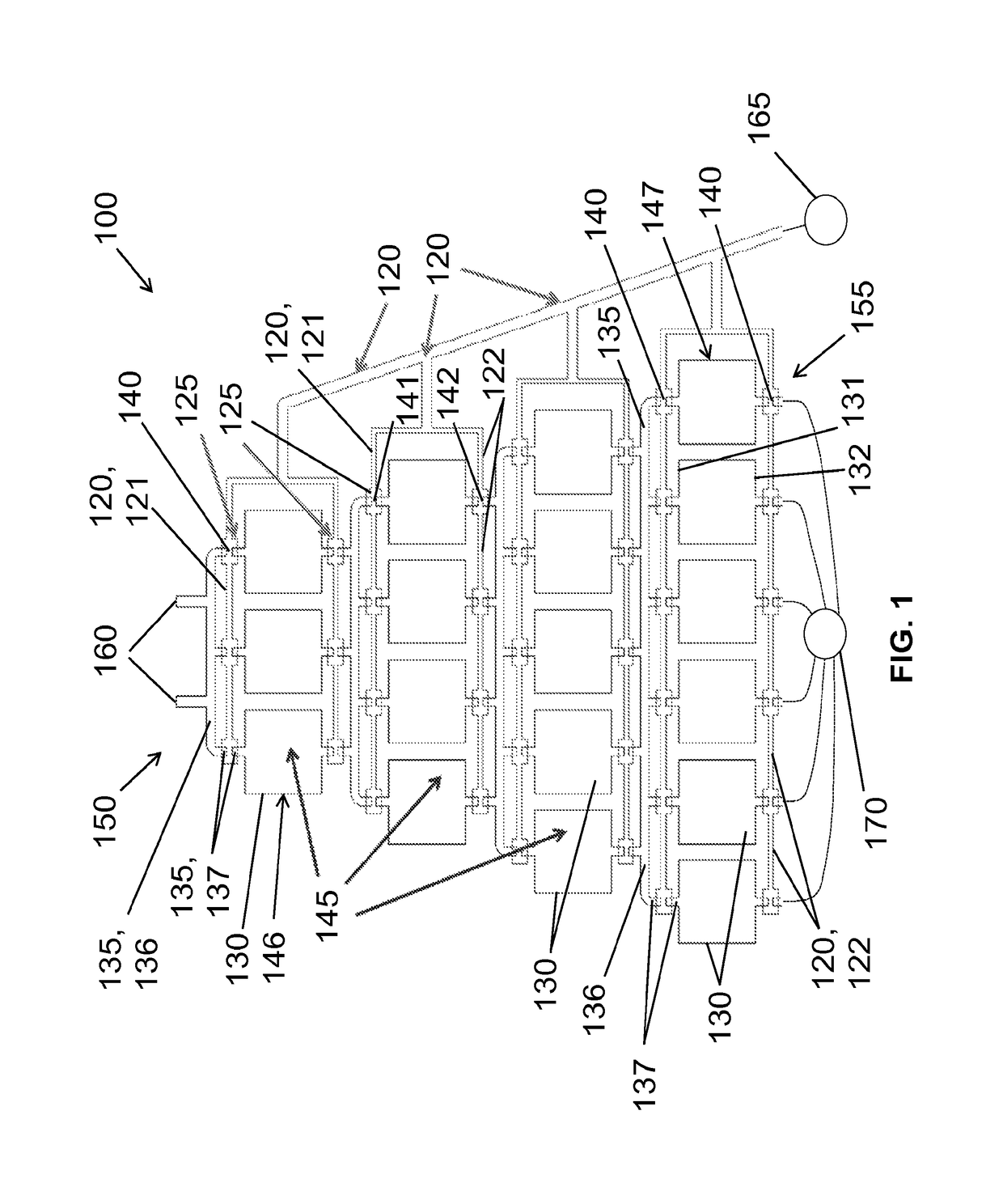
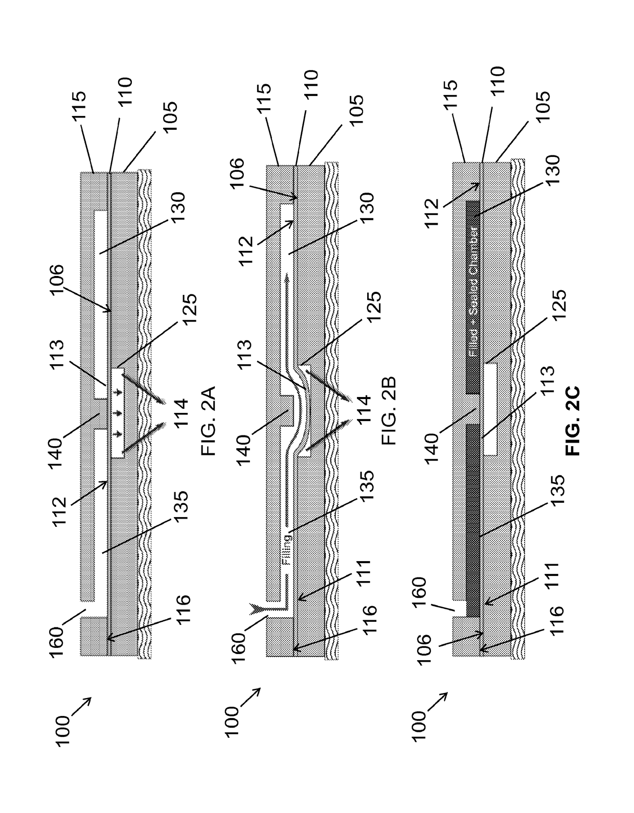
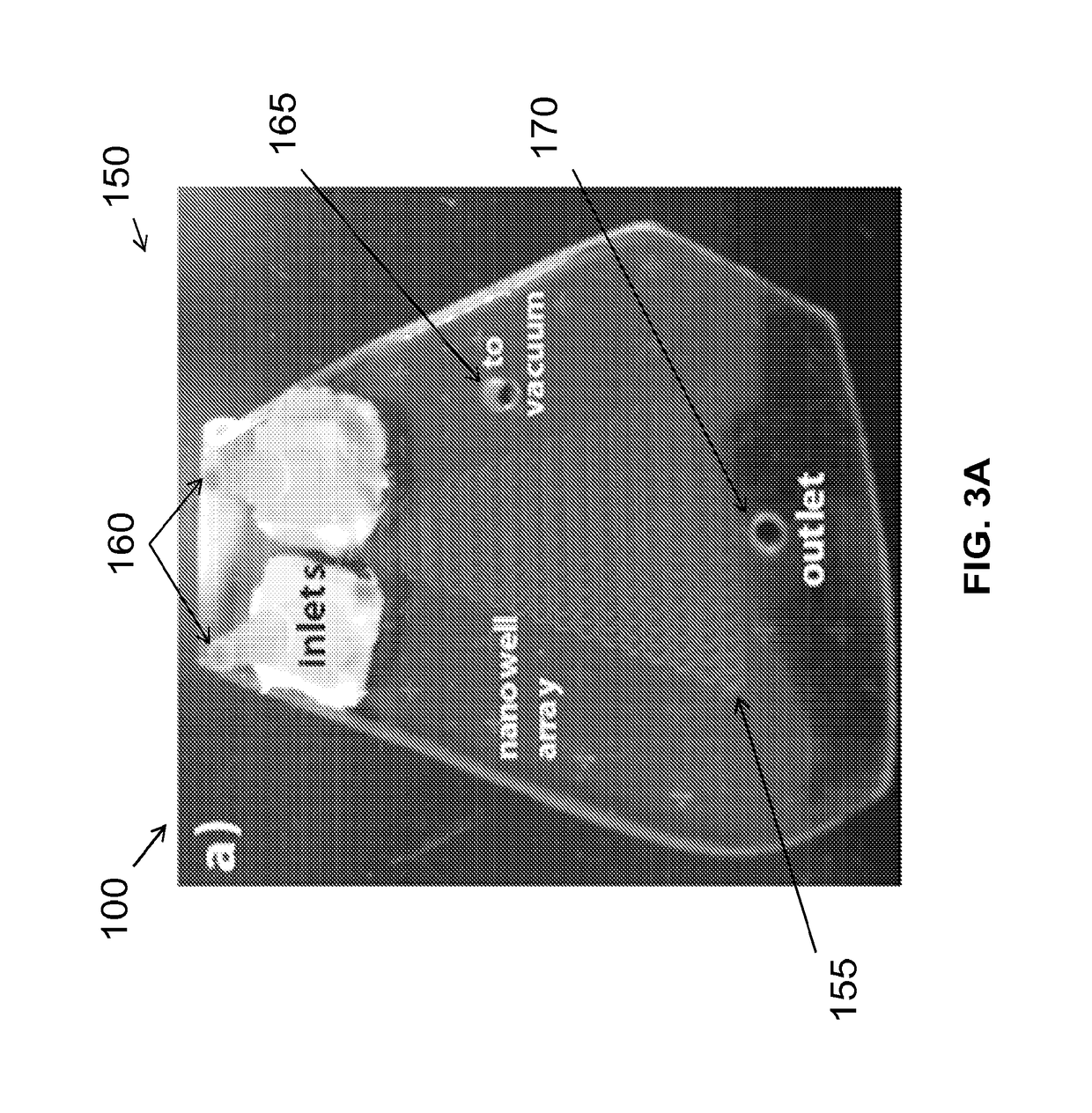
[0030]Example microfluidic apparatus, systems and methods for microfluidic crystallization based on gradient mixing are described herei...


PUM

PropertyMeasurementUnit
concentrationaaaaaaaaaa

Abstract

A microfluidic apparatus, systems and methods for microfluidic crystallization based on gradient mixing. In one embodiment, the apparatus includes (a) a first layer, (b) a plurality of first channels and a plurality of vacuum chambers both arranged in the first layer, where the plurality of vacuum chambers are each coupled to at least one of the first channels, (c) a membrane having first and second surfaces, where the first surface of the membrane is coupled to the first layer, (d) a second layer coupled to the second surface of the membrane, (e) a plurality of wells and a plurality of second channels both arranged in the second layer, where the wells are each coupled to at least one of the plurality of second channels and (f) a plurality of barrier walls each disposed in the plurality of second channels and arranged opposite to one of the plurality of vacuum chambers.

Description

CROSS-REFERENCE TO RELATED APPLICATIONS[0001]This application claims the benefit of the filing date of International PCT Application No. PCT / US2015 / 050616, filed Sep. 17, 2015, that claims priority to U.S. Provisional Application No. 62 / 051,642 for a Microfluidic Crystallization Array based on Gradient Mixing, filed Sep. 17, 2014, which are hereby incorporated by reference in their entirety.STATEMENT OF GOVERNMENT FUNDING[0002]This invention was made with government support under R01-GM095583 awarded by the National Institute of Health and under 1231306 awarded by the National Science Foundation BioXFEL Science and Technology Center. The government has certain rights in the invention.BACKGROUND OF THE INVENTION[0003]Protein crystallography is on the brink of being taken to a new level with the introduction of the X-ray free electron laser, which may be used to solve the structures of complex proteins via serial femtosecond crystallography, for example. Sample crystal characteristics...

Claims


Application Information

Patent Timeline
Patent Type & Authority Patents(United States)
IPC IPC(8): C30B7/08B01L3/00G01N1/38
CPCB01L3/502761B01L3/502715B01L3/502738G01N1/38B01L3/50273B01L2400/0655B01L2200/0652B01L2300/0654B01L2300/0816B01L2300/0848B01L2300/0861B01L2300/0864B01L2300/0867B01L2300/0887B01L2300/0896B01L2300/123B01L2300/16B01L2400/049B01L2400/0424B01L2400/0487
Inventor ROS, ALEXANDRAABDALLAH, BAHIGE G.
Owner ARIZONA STATE UNIVERSITY
Why Eureka
Try Eureka