Optical fiber connector ferrule assembly having dual reflective surfaces for beam expansion and expanded beam connector incorporating same

a technology of optical fiber and ferrules, which is applied in the direction of optics, fibre mechanical structures, instruments, etc., can solve the problems of reducing the efficiency of light transmission between the optical fiber pair, affecting the transmission of light, and increasing the relative size difference between the dust or debris and the beam, so as to achieve low insertion and return losses, high reliability, and convenient use

Active Publication Date: 2019-03-26
SENKO ADVANCED COMPONENTS
View PDF7 Cites 7 Cited by
  • Summary
  • Abstract
  • Description
  • Claims
  • Application Information

AI Technical Summary

Benefits of technology

[0025]The present invention provides an optical fiber ferrule or ferrule assembly for expanding light beam in an optical fiber expanded beam connector, which overcomes many of the drawbacks of the prior art ferrules and connectors, including low insertion and return losses, ease of use and high reliability with low environmental sensitivity, and which can be fabricated at low cost. Given the configuration of the inventive ferrules, the foot-print or form factor of the housing of the optical fiber connector incorporating the inventive ferrule for multi-fibers can be similar to that of housings that currently use prior art cylindrical ferrules designed for only a single fiber (i.e., the inventive ferrules may be incorporated in industry standard connector housings designed for single fiber, such as SC, FC, ST, SMA, LC, Dual LC, etc., type housings.)
[0034]In another aspect of the present invention, the ferrule components and / or sleeve are precision formed by high throughput processes, such as stamping a metal blank material. In one embodiment, the ferrule body is made of a metal material, which may be chosen to have high stiffness (e.g., stainless steel), chemical inertness (e.g., titanium), high temperature stability (nickel alloy), low thermal expansion (e.g., Invar), or to match thermal expansion to other materials (e.g., Kovar for matching glass). Each ferrule halve may be stamped to form a unitary or monolithic body, which does not require further attachment of sub-components within the ferrule halve.
[0036]The ferrule in accordance with the present invention overcomes many of the deficiencies of the prior art, resulting in an optical fiber expanded beam connector with low insertion and return losses, which provides ease of use and high reliability with low environmental sensitivity, and which can be fabricated at low cost.

Problems solved by technology

In such applications, various factors may reduce the efficiency of light transmission between the optical fiber pair, such as irregularities, burrs or scratches in the fiber end faces, misalignment of the optical fiber pair, as well as dust or debris between the optical fibers at the mating interface.
Due to the small optical path relative to the size of any foreign objects such as dust or debris, any such foreign objects will interfere with the transmission of light.
By expanding the beam, the relative size difference between the dust or debris and the beam is increased which thus reduces the impact of any dust or debris as well as any misalignment on the efficiency of the light transmission.
Currently, it is generally accepted that prior art optical fiber connectors cost too much to manufacture and the reliability and loss characteristics are more to be desired.
The lens in an expanded beam connector is an additional component, which is required to be optically coupled to the end face of the optical fiber in an assembly, thus requiring additional component costs and additional manufacturing costs.
Prior art expanded beam connectors still result in relatively high insertion losses and return losses.

Method used


Image

  • Optical fiber connector ferrule assembly having dual reflective surfaces for beam expansion and expanded beam connector incorporating same
  • Optical fiber connector ferrule assembly having dual reflective surfaces for beam expansion and expanded beam connector incorporating same
  • Optical fiber connector ferrule assembly having dual reflective surfaces for beam expansion and expanded beam connector incorporating same

Examples


Embodiment Construction

[0038]This invention is described below in reference to various embodiments with reference to the figures. While this invention is described in terms of the best mode for achieving this invention's objectives, it will be appreciated by those skilled in the art that variations may be accomplished in view of these teachings without deviating from the spirit or scope of the invention.

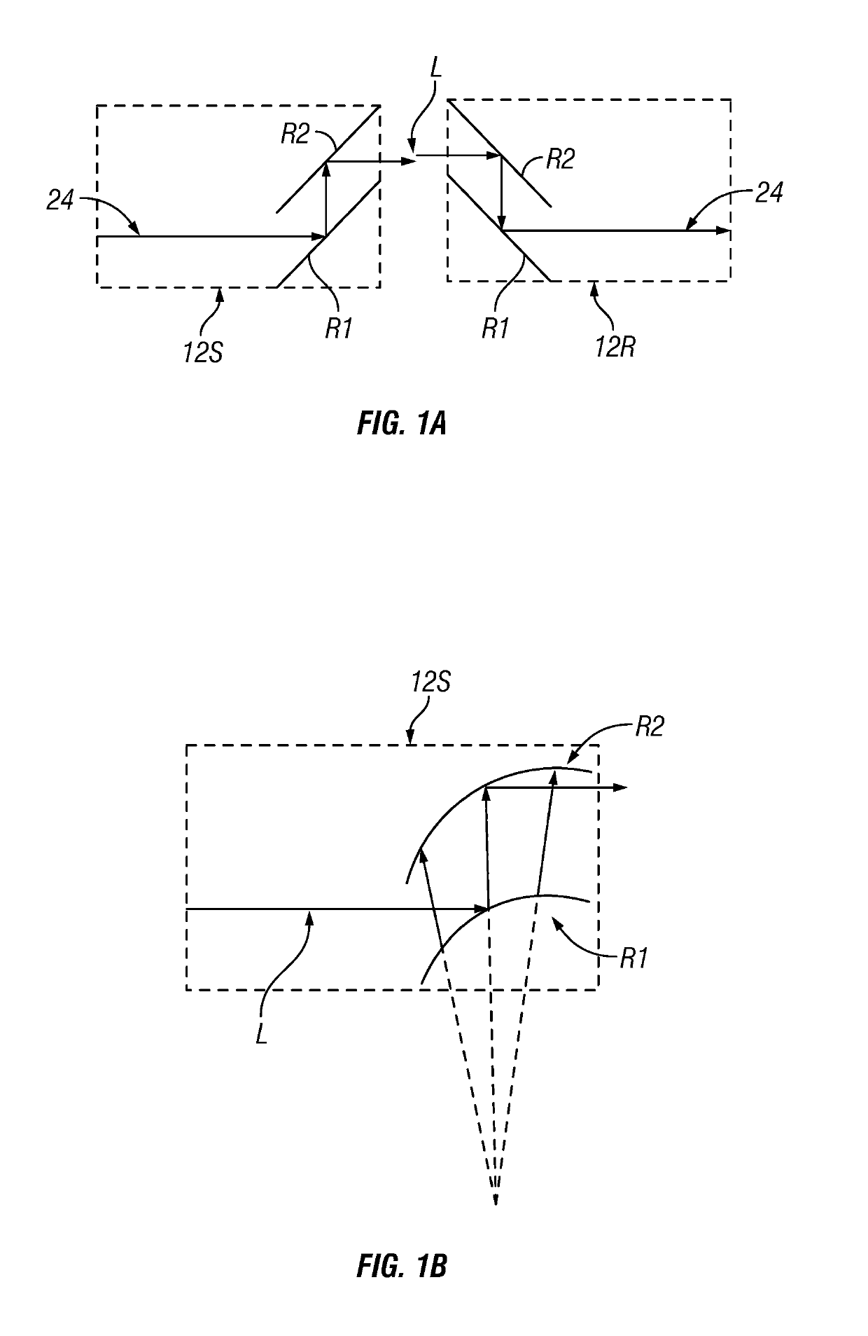
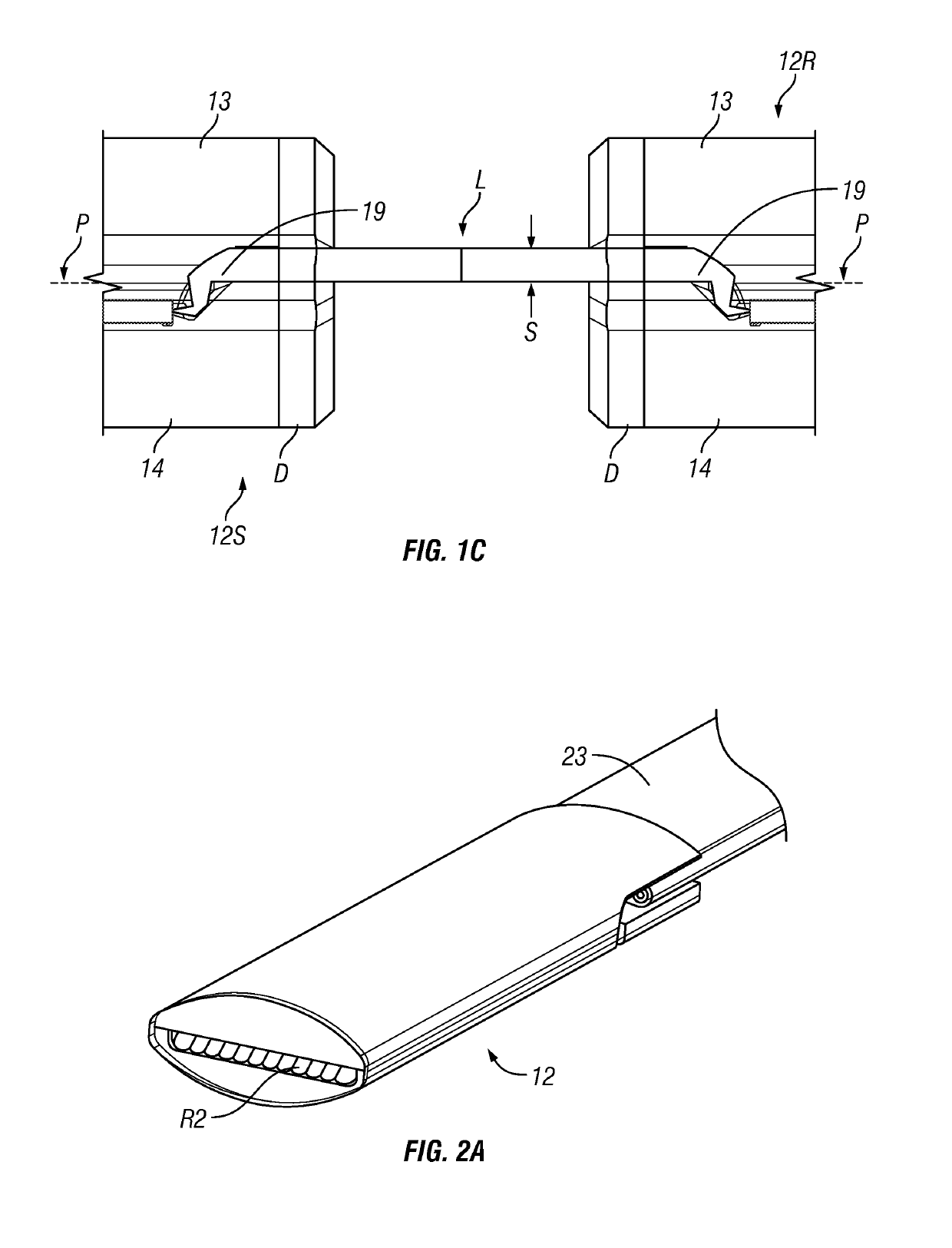
[0039]FIGS. 1A-1C are schematic views illustrating the optical path between two aligned ferrule assemblies incorporated in optical fiber connectors in accordance with one embodiment of the present invention. For simplicity, hereinafter, “ferrule assembly” will be referred simply as a “ferrule”, which has two ferrule halves. Further details on the ferrule will be disclosed hereinbelow.

[0040]FIG. 1A schematically illustrates the light beam L from a source ferrule 12S to a receiving ferrule 12R. The source ferrule 12S and the receiving ferrule 12R each includes a pair of integrated reflective surfaces R1 (e.g...


PUM


Abstract

An expanded beam ferrule includes a first ferrule halve having first reflective surfaces and a second ferrule halve having second reflective surfaces, which together retain optical fibers. The pair of reflective surfaces output collimated light parallel to the mid-plane of the ferrule. An external sleeve aligns the external surface of two similar ferrules, with corresponding second reflective surfaces of the ferrules facing each other. Output light from an optical fiber held in one ferrule is bent twice by the pair of reflective surfaces, with beam divergence after the first bent, and collimation after the second bent. The collimated light is transmitted to the facing second reflective surface in a facing second ferrule aligned by the sleeve, which is subject to optical reshaping in reverse to that undertaken in the first ferrule, so as to converge and focus light to input to the optical fiber held in the other ferrule.

Description

PRIORITY CLAIM[0001]This application claims the priority of U.S. Provisional Patent Application No. 62 / 376,381 filed on Aug. 17, 2016, which is fully incorporated by reference as if fully set forth herein. All publications noted below are fully incorporated by reference as if fully set forth herein.GOVERNMENT RIGHTS[0002]This invention was made with government support under Contract No. DE-SC0009617 awarded by DEPARTMENT OF ENERGY. The government has certain rights in the invention.BACKGROUND OF THE INVENTION[0003]1. Field of the Invention[0004]The present invention relates to optical beam expanded beam connectors, in particular ferrule assemblies in expanded beam connectors.[0005]2. Description of Related Art[0006]There are many advantages of transmitting light signal via optical fiber waveguides and the use thereof is diverse. Single or multiple fiber waveguides may be used simply for transmitting visible light to a remote location. Complex telephony and data communication systems...

Claims


Application Information

Patent Timeline
Patent Type & Authority Patents(United States)
IPC IPC(8): G02B6/38G02B6/44G02B6/42
CPCG02B6/3818G02B6/383G02B6/3839G02B6/3849G02B6/3874G02B6/3887G02B6/3893G02B6/4214G02B6/4403G02B6/3885G02B6/3865G02B6/3888
Inventor LI, SHUHEVALLANCE, ROBERT RYANDANNENBERG, RAND D.GEAN, MATTHEWKLOTZ, GREGORY L.
Owner SENKO ADVANCED COMPONENTS
Why Eureka
Try Eureka