
Process for manufacturing a leadless feedthrough for an active implantable medical device

a technology of lead-free feedthrough and implantable medical devices, which is applied in the direction of manufacturing tools, soldering apparatus, therapy, etc., can solve the problems of reducing current carrying capacity and prior art failure to explain hermetic feedthroughs, and achieves small conductive pathways/vias, reduces residual stress, and enhances structural stability of pressed powder

Active Publication Date: 2019-04-02
WILSON GREATBATCH LTD
View PDF89 Cites 7 Cited by
  • Summary
  • Abstract
  • Description
  • Claims
  • Application Information

AI Technical Summary

Benefits of technology

This approach provides a cost-effective, reliable, and biocompatible solution with reduced risk of hermeticity loss, enhanced thermal stability, and increased conductive pathway density, addressing the limitations of existing designs by ensuring sustainable hermeticity and improved performance under demanding conditions.

Problems solved by technology

The prior art fails to explain a hermetic feedthrough insulator manufacturing process that laminates all the layers first and then machines vias, counterbores, cavities and the ceramic outer diameter of the insulator after lamination.
These prior art necessities significantly reduce current carrying capacity and demonstrate significant variation via to via and part to part all of which stress optimal performance of implantable devices and sometimes precludes use of these prior art feedthroughs in demanding applications such as cardioverters / defibrillators that deliver high voltage and high current shock.

Method used


Image

  • Process for manufacturing a leadless feedthrough for an active implantable medical device
  • Process for manufacturing a leadless feedthrough for an active implantable medical device
  • Process for manufacturing a leadless feedthrough for an active implantable medical device

Examples


Embodiment Construction

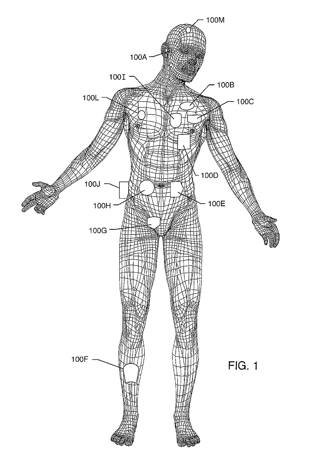
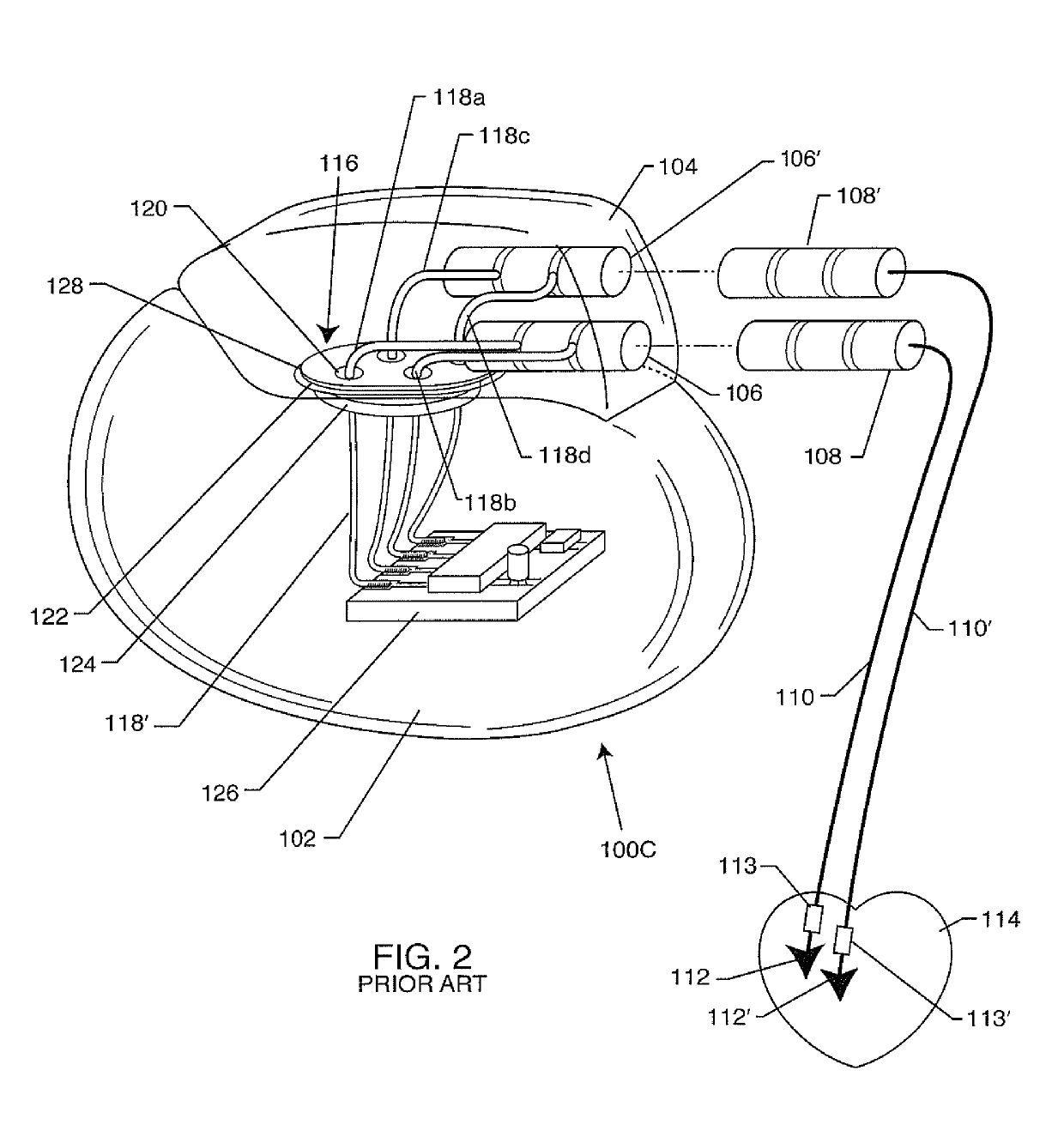
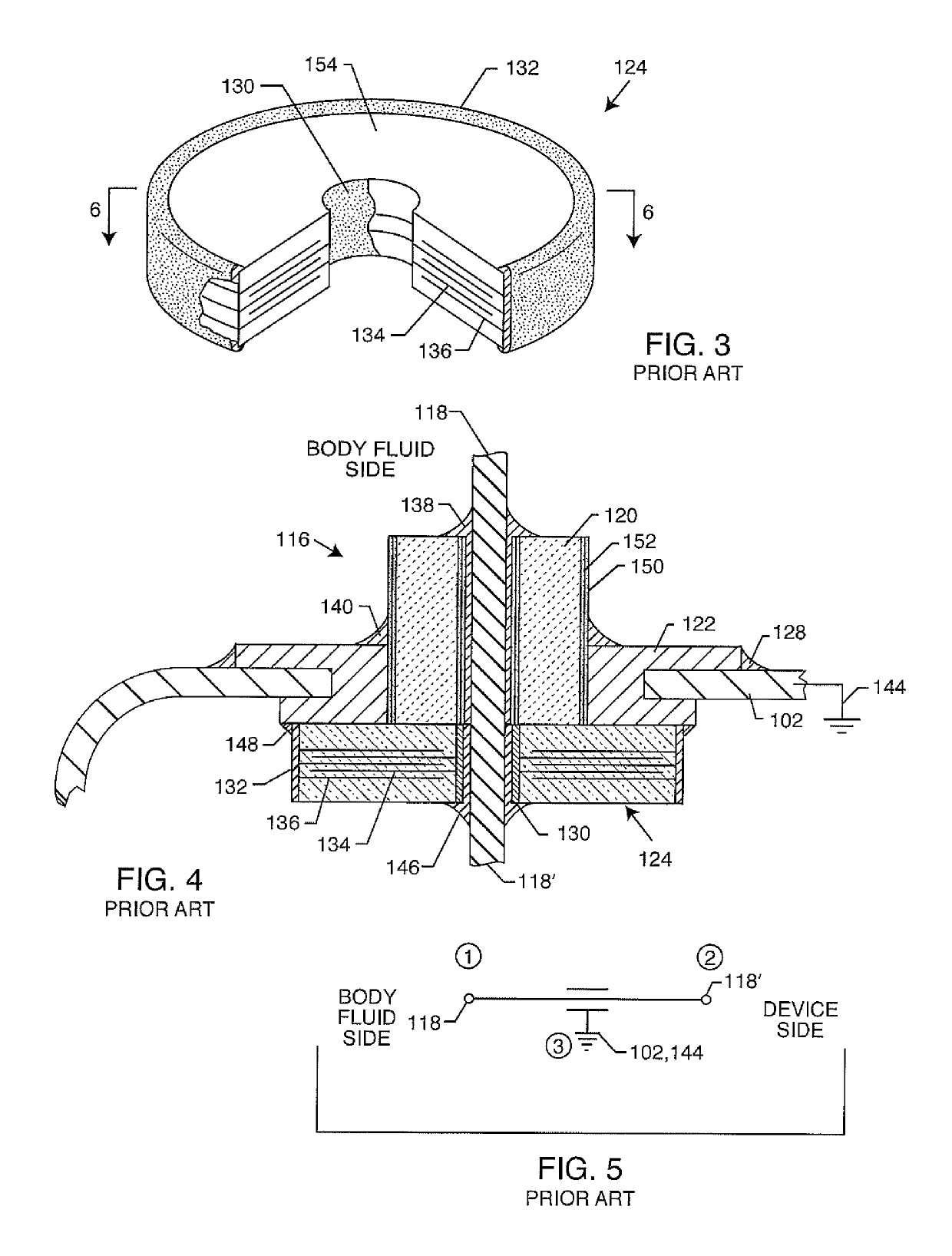
[0281]As previously described in-whole or in-part within U.S. provisional applications 62 / 443,011, 62 / 450,187, 62 / 461,872, 62 / 552,363 and 62 / 613,500 filed Jan. 6, 2017, Jan. 25, 2017, Feb. 22, 2017, Aug. 30, 2017 and Jan. 4, 2018 respectively, the present invention now includes various embodiments of different options. The following detailed description is now for 110 sheets of drawings, which are labeled FIG. 1 through FIG. 176. Certain FIGURES illustrate one option while other FIGURES illustrate another option. Some FIGURES illustrate several options in just one figure. It will be understood that any of the FIGURES that describe the present invention are applicable to any of the options. In other words, the FIGURES illustrate a variety of ways in which the various options can be reduced to practice.

[0282]FIG. 1 illustrates various types of active implantable and external medical devices 100 that are currently in use. FIG. 1 is a wire formed diagram of a generic human body showing ...


PUM


Abstract

A method of manufacturing a feedthrough dielectric body for an active implantable medical device includes the steps of: a) forming an alumina ceramic body in a green state, or, stacking upon one another discrete layers of alumina ceramic in a green state and pressing; b) forming at least one via hole straight through the alumina ceramic body; c) filling the at least one via hole with a ceramic reinforced metal composite paste; d) drying the alumina ceramic body and the ceramic reinforced metal composite paste; e) forming a second hole straight through the ceramic reinforced metal composite paste being smaller in diameter in comparison to the at least one via hole; f) filling the second hole with a substantially pure metal paste; g) sintering the alumina ceramic body, the ceramic reinforced metal composite paste and the metal paste; and h) hermetically sealing the feedthrough dielectric body to a ferrule.

Description

CROSS-REFERENCE TO RELATED APPLICATIONS[0001]This continuation-in-part application claims priority to application Ser. No. 15 / 797,278 filed on Oct. 30, 2017. This application also claims priority to the following provisionals:[0002]1) 62 / 443,011, filed on Jan. 6, 2017;[0003]2) 62 / 450,187, filed on Jan. 25, 2017;[0004]3) 62 / 461,872, flied on Feb. 22, 2017;[0005]4) 62 / 552,363, filed on Aug. 30, 2017, and[0006]5) 62 / 613,500, filed on Jan. 4, 2018.The entire contents of all applications listed above are fully incorporated herein with these references.FIELD OF THE INVENTION[0007]The present invention generally relates to implantable medical devices and hermetic terminal subassemblies. More particularly, the present invention relates a hermetic terminal for an active implantable medical device having a composite co-fired filled via with a brazed body fluid side leadwire.BACKGROUND OF THE INVENTION[0008]A wide assortment of active implantable medical devices (AIMDs) are presently known and...

Claims


Application Information

Patent Timeline
Patent Type & Authority Patents(United States)
IPC IPC(8): A61N1/37C04B41/45H01B17/30A61N1/375B23K26/21C04B41/88H01B19/02C04B41/00B23K1/008B23K1/19B23K26/32B23K35/00B23K1/00C04B41/51B22F7/04B23K101/36B23K103/14
CPCH01B17/30B23K1/008B23K1/0016B23K1/19B23K26/21B23K26/32C04B41/0072C04B41/4578C04B41/5122C04B41/5177C04B41/5194C04B41/88H01B19/02A61N1/3754B23K2103/14B22F7/04B23K2101/36B22F7/08
Inventor SEITZ, KEITH W.RENSEL, DALLAS J.HOHL, BRIAN P.CALAMEL, JONATHANTANG, XIAOHONGSTEVENSON, ROBERT A.FRYSZ, CHRISTINE A.MARZANO, THOMASWOODS, JASONBRENDEL, RICHARD L.
Owner WILSON GREATBATCH LTD
Learn More