Electronic part mounting heat-dissipating substrate

a technology for heat dissipation substrates and electronic parts, applied in the field of substrates, can solve the problems of insufficient performance, limited heat dissipation characteristics, and heat generation, and achieve the effects of suppressing temperature rise, reducing circuit wiring resistance, and effectively suppressing heat generation amoun

Inactive Publication Date: 2019-04-02
NSK LTD
View PDF63 Cites 1 Cited by
  • Summary
  • Abstract
  • Description
  • Claims
  • Application Information

AI Technical Summary

Benefits of technology

[0032]According to an electronic part mounting heat-dissipating substrate according to the present invention, lead frames of wiring pattern shapes of a circuit on which electronic parts are mounted are formed by a method for punching by press-working or laser-processing a conductor plate made by using metal such as aluminum or copper. Further, the gap between the lead frames is entirely fixed by a heat conductive resin or the like. Consequently, according to the configuration, it is not necessary to provide a special step-processed portion at a heat-generating electronic part mounted / equipped portion.
[0033]Thus, according to the electronic part mounting heat-dissipating substrate of the present invention, the electronic parts such as the power semiconductor can be directly solder-bonded on the lead frames of the wiring pattern shapes composed of the conductor plate to compose a circuit. Further, the larger plate thickness can also be secured for the conductor plate which forms the lead frames. In this way, even when the electronic part mounting heat-dissipating substrate is used for a circuit in which a large current flows, it is possible to reduce a circuit wiring resistance and effectively suppress a heat generation amount. In addition, it is possible to suppress a temperature rise which is a transient phenomenon such as a sudden heat generation caused when a large current flows to the power device to support sudden steering in an electric power steering apparatus.
[0034]That is, as illustrated in, for example, FIG. 22A, a conventional aluminum substrate 2100 is formed by forming an insulating layer on an upper surface of an aluminum layer, and mounting electronic parts EC such as FETs and a capacitor on patterning wires such as a copper foil layer formed on an upper layer of the insulating layer. A lower surface of the aluminum layer is disposed in a case with a TIM (Thermal Interface Material) described below interposed therebetween. By contrast with this, a substrate 2200 according to the present invention illustrated in FIG. 22B is composed of lead frames 110 and insulating members 130. The respective electronic parts EC can be directly mounted on the lead frames 110 by the SMT (Surface Mount Technology), and can be manufactured by a conventional reflow device. Further, adopting such a structure results in improving a transient heat characteristic since the substrate according to the present invention differs from the conventional aluminum substrate in an insulating layer which is the TIM and the lead frames which are heat spreaders. Furthermore, when this substrate according to the present invention is used, and is connected with another control substrate, it is possible to remove custom parts (terminal terminals) and reduce the cost. Still further, upon comparison between the present invention and a conventional transfer module, a high-capacity electrolytic capacitor can be mounted on the substrate according to the present invention. Consequently, it is also possible to provide advantages that electric characteristics improve and another substrate does not need to be provided for the high-capacity electrolytic capacitor.
[0035]Further, the heat generated by the electronic parts mounted on the substrate according to the present invention is dissipated by the conductor plate composing the substrate and the insulating member. Then, when necessary, this heat can be dissipated to an external thermal mass through the composite insulating material for which a highly heat conductive heat-conductive material (TIM (Thermal Interface Material)) of a housing of a control unit in which the substrate is housed is used. Thus, a synergy effect provided by the housing of the control unit in which the substrate is housed can further improve the heat dissipation.
[0036]Furthermore, the insulating member according to the present invention is made of the highly heat conductive composite-insulating material, and the insulating layer formed between the lead frames of the circuit pattern shapes can be formed thick. Accordingly, it is possible to provide an effect that it is possible to reduce a distribution capacitance such as a capacitor between patterns.
[0037]According to the present invention, both surfaces of the electronic part mounting heat-dissipating substrate are used as the part arrangement surface, and the reductant circuits are disposed and formed on the both surfaces of the electronic part mounting heat-dissipating substrate. In a case of using the common lead frames which are used in the common circuit wiring of the reductant circuits which are disposed on the both surfaces, since the maximum current amount which are used in one system decrease up to about 50%, a miniaturization of the electronic parts such as an FET is possible. In a case of using the inverter of the three-phase brushless motor in the electric power steering apparatus, a structure of a partial reductant system is possible. If needed, by using (cross driving) the combination of the first surface and the second surface of the reductant circuits which are mounted both surfaces and are configured to the above three-phase, it is possible to improve fault tolerance.

Problems solved by technology

Further, it is an important problem to efficiently dissipate heat generated due to a loss of the highly density mounted power semiconductor to convert the circuits for which the power semiconductors are used into the dedicated substrates.
Therefore, when the thin conductor foil which is approximately 70 [μm] is used, and is used for a circuit for which the power semiconductor in which a large current flows is used, a wiring resistance causes a problem.
Further, according to the above configuration, a heat dissipation characteristic is limited by the insulating layer of a low heat transfer coefficient.
Therefore, there is a problem that it is not possible to provide a sufficient performance.

Method used


Image

  • Electronic part mounting heat-dissipating substrate
  • Electronic part mounting heat-dissipating substrate
  • Electronic part mounting heat-dissipating substrate

Examples


Embodiment Construction

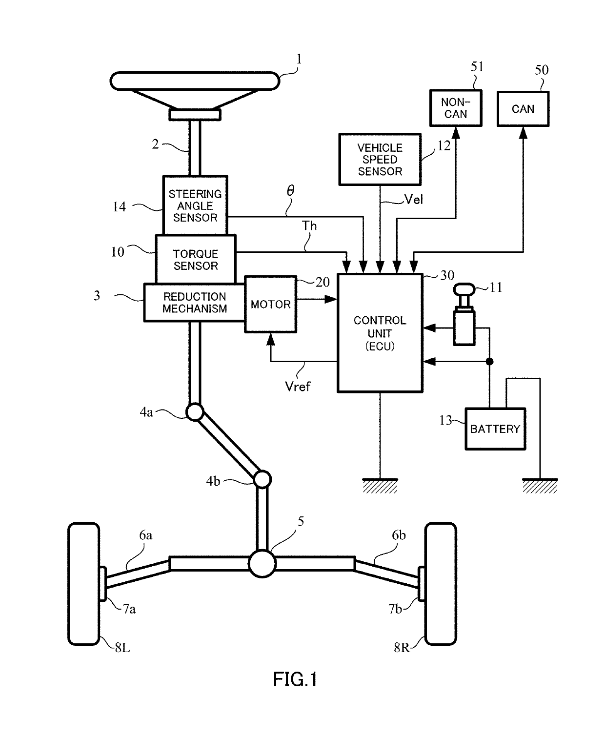
[0065]An embodiment of the present invention will be described by using a case where is used for a control unit (ECU) of an electric power steering apparatus mounted on a vehicle as an example.

[0066]In this regard, the electric power steering apparatus (EPS) applies a rotational force of an electric motor as a steering assist force (an assist force) to a steering mechanism of the vehicle, and applies a driving force of the motor as the steering assist force to a steering shaft or a rack shaft with a transmission mechanism such as gears and a belt via a reduction mechanism. Further, such the electric power steering apparatus accurately generates a torque of the steering assist force and therefore performs a feedback control of a motor current.

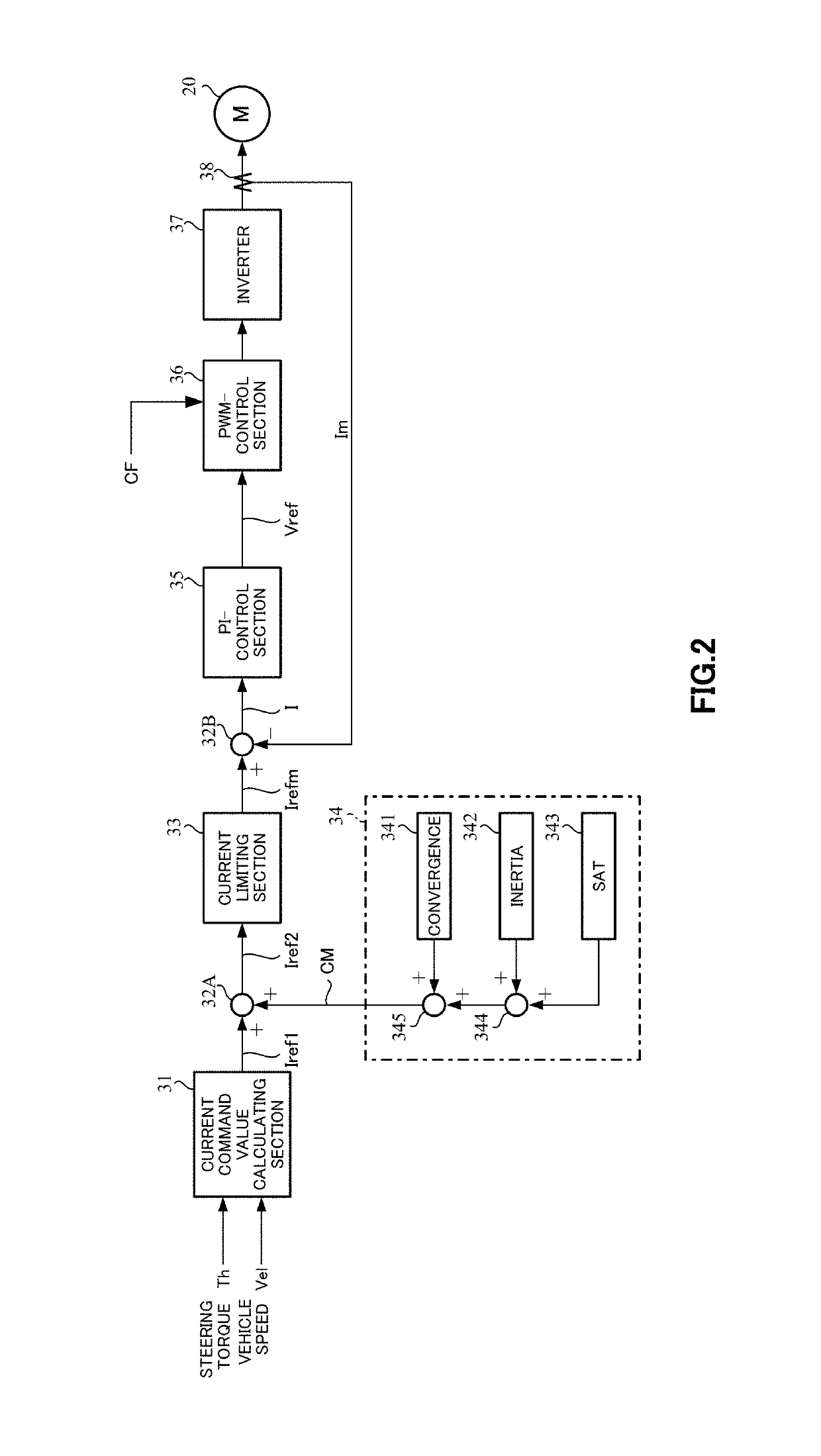
[0067]The above feedback control is a control to adjust a motor applying voltage in order to decrease a difference between a steering assist command value (a current command value) and a motor current detection value. The motor applying voltage ...


PUM


Abstract

An electronic heat-dissipating substrate including: lead frames of wiring pattern shapes on a conductor plate; and an insulating member between the lead frames. A plate surface of the lead frames and a top surface of the insulating member form one continuous surface. The part arrangement surface is on both surfaces of the electronic part mounting heat-dissipating substrate, a reductant circuit which includes at least similar dual-system circuit is formed on the electronic part mounting heat-dissipating substrate, a first-system circuit of the dual-system circuit is formed on a first surface of the electronic part mounting heat-dissipating substrate, a second-system circuit of the dual-system circuit is formed on a second surface of the electronic part mounting heat-dissipating substrate, and the common lead frames used in a portion of a circuit wiring are used to the first surface and the second surface of the electronic part mounting heat-dissipating substrate.

Description

CROSS REFERENCE TO RELATED APPLICATIONS[0001]This application is a National Stage of International Application No. PCT / JP2015 / 082704, filed Nov. 20, 2015, claiming priorities based on Japanese Patent Application Nos. 2014-235691, filed Nov. 20, 2014, 2015-140106, filed Jul. 14, 2015, 2015-216153, 2015-216154, 2015-216155 and 2015-216156, filed Nov. 2, 2015 respectively, 2015-216396 and 2015-217012, filed Nov. 4, 2015 respectively, 2015-222242, 2015-222243 and 2015-222246, filed Nov. 12, 2015 respectively, the contents of all of which are incorporated herein by reference in their entirety.TECHNICAL FIELD[0002]The present invention relates to a substrate which reduces a wiring resistance and improves a heat dissipation and on which electronic parts are mounted or equipped. More particularly, the present invention relates to an electronic part mounting heat-dissipating substrate in which insulating members are filled by punching between lead frames of a conductor plate formed in the le...

Claims


Application Information

Patent Timeline
Patent Type & Authority Patents(United States)
IPC IPC(8): H01L23/495G01R1/20H01L23/498H01L49/02H01L25/07H01L23/00H01L23/12H01L23/36H01L23/50H01L23/48H05K1/18H05K3/20H02K11/33B62D5/04
CPCH01L23/49568B62D5/0406G01R1/203H01L23/12H01L23/36H01L23/48H01L23/49524H01L23/49531H01L23/49537H01L23/49558H01L23/49861H01L23/50H01L24/34H01L24/37H01L25/071H01L28/20H02K11/33H05K2201/09881H05K3/202H05K1/181H01L2224/34H01L2224/37147H01L2224/37599H01L2924/00014H01L2924/00012H01L23/49541H01L23/49548H01L2224/37124H01L2224/84801H01L24/84H01L2224/40225H01L24/40
Inventor SHIMAKAWA, SHIGERUSUNAGA, TAKASHISEKINE, TAKAAKIKOGURE, TERUYOSHISUZUKI, RYOICHI
Owner NSK LTD
Why Eureka
Try Eureka