Hot air oven

a technology of oven and hot air, which is applied in the field of hot air oven, can solve the problems of increasing running costs, occupying a lot of space, and increasing efficiency, and achieves the effects of reducing running costs, improving efficiency, and reducing the footprin

Active Publication Date: 2019-04-16
REVENT INT AB
View PDF39 Cites 25 Cited by
  • Summary
  • Abstract
  • Description
  • Claims
  • Application Information

AI Technical Summary

Benefits of technology

[0012]The hot air oven according to the present invention has proven to improve the efficiency in relation to when conventional heat exchangers are used. It is then possible to produce baker's ovens with a smaller footprint and / or lower running costs as increased efficiency has led to less fuel being required to heat the same amount of cooking air.
[0013]Bakers oven have the special requirements where the outer side (where the baking air flows) is of a turbulent kind, with high thermal transfer capabilities. Whereas the inner side has a significant lower air mass flow (approx. one tenth) the large inner surface improves efficiency by raising heat flux. Hence making the surface larger on the outside doesn't improve efficiency; rather it increases foot print and costs.
[0014]As temperature difference between exhaust gas and baking air (ΔT) decreases more surface is needed. When ΔT is high, low surface area is needed; the higher temperature raises the heat flux on the heating element. However, higher ΔT will increase temperature on the surface, which will force the use of more exclusive materials, such as heat resistant steel. The present invention makes it possible to optimize the inner surface area so that the temperature on the other surface matches the optimal range for the materials used.
[0015]In one embodiment of the invention the inner surface area of the heat exchanger tubes is reduced in special locations. For example, close to the burner to decrease heat flux and the outer surface temperature. This feature improves the control of the temperature and to adjust the temperature to an optimal range.

Problems solved by technology

While conventional heat exchangers are relatively compact and have good efficiency they still take up a lot of space and are a major contributor to the foot print of a baker's oven.
Such measures may increase the efficiency slightly but at the cost of increased air friction on the cold side which requires the use of a larger fan and increased running costs.
However, none of the background prior art documents includes any heat exchanger tubes specifically adapted for use in hot air ovens.

Method used


Image

  • Hot air oven
  • Hot air oven
  • Hot air oven

Examples


first embodiment

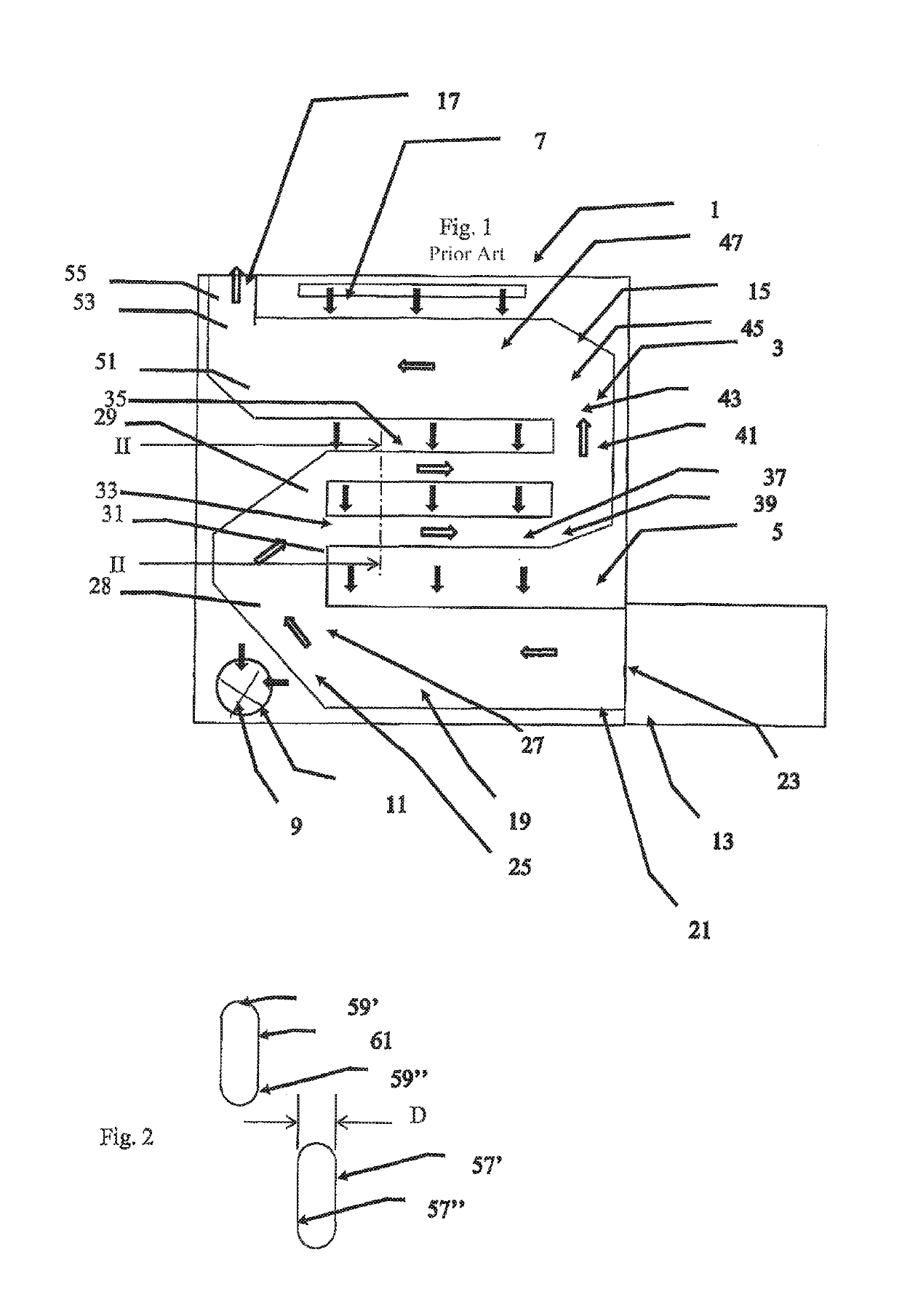
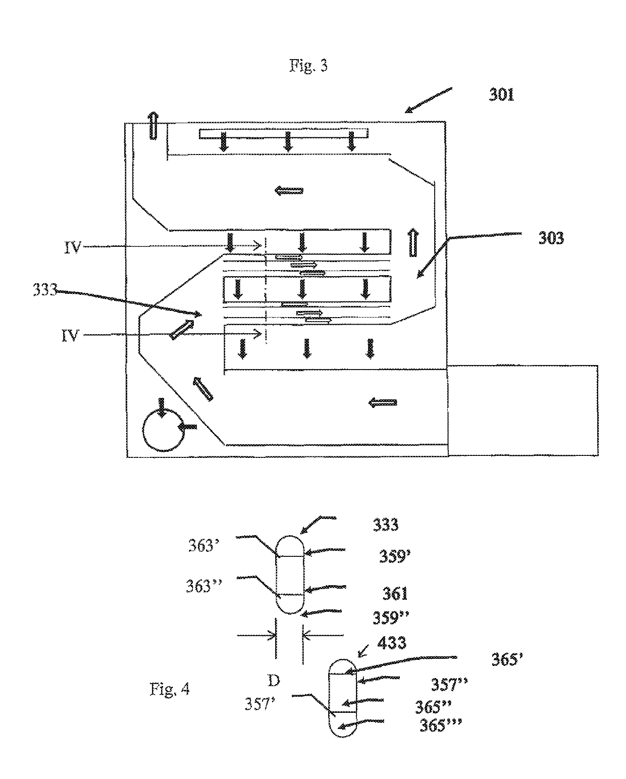
[0026]FIG. 3 shows schematically a simplified side view of a baker's oven 301 of the type shown in FIG. 1 but provided with a cross-flow tube heat exchanger 303 with heat exchanger tubes 333 in accordance with the present invention.

[0027]As can be seen in FIG. 4, the heat exchanger tubes 433 have the same external shape as the conventional tubes, i.e. a cross-section with two straight and parallel long sides 357′ and 357″, separated by a distance D, and connected by a pair of short ends 359′ and 359″. In this embodiment of the invention the short ends are convex and have a diameter of curvature D. The thin tube wall 361 of each heat exchanger tube 333 is made of a material with good thermal conductivity and corrosion resistance, for example a metal such as pure or alloyed aluminium, copper or iron.

[0028]The interior of these heat exchanger tubes are provided with one or more—in this example two—longitudinally extending interior walls 363′, 363″. Each interior wall stretches from one...

second embodiment

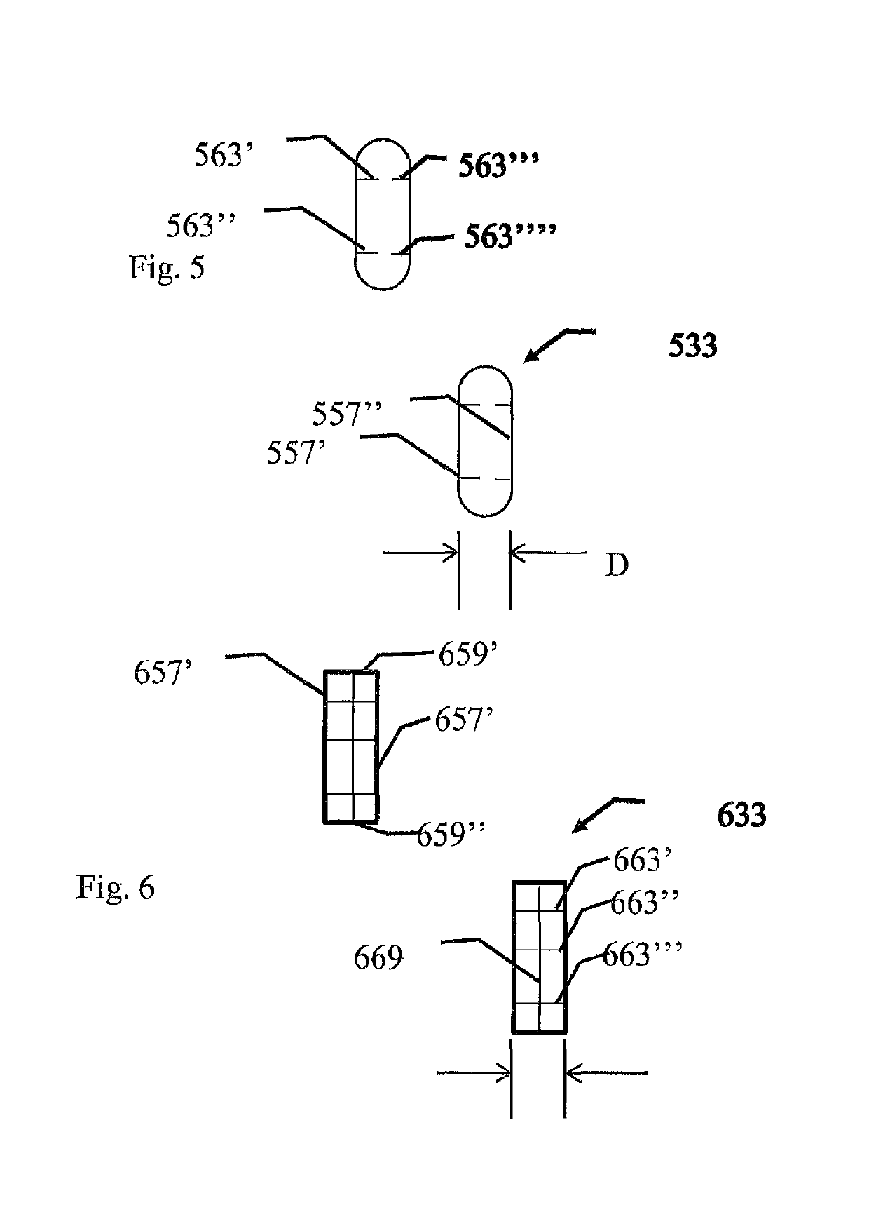
[0029]FIG. 5 shows a cross-section through a pair of heat exchanger tubes 533 in accordance with the present invention. In this embodiment, the interior of these heat exchanger tubes are provided with one or more—in this example four—interior longitudinally extending walls 563′, 563″, 563″′, 563″″. Each interior wall stretches from one long side 557′ towards the opposite long side 557″ but does not contact it. This divides the heat exchanger tube into three open (i.e. there is nothing which prevents exhaust gas from flowing from one compartment into another compartment) elongated compartments 565′, 565″, 565″′ though which the exhaust gases flow. The innermost ends and / or the exposed surfaces of the interior walls may be roughened or shaped to induce turbulence in order to aid the transfer of heat energy from the exhaust gas to the interior wall.

[0030]FIG. 6 shows a cross-section through a second embodiment of a heat exchanger tube 633 in accordance with the present invention. In th...


PUM


Abstract

In order to improve the transfer of heat from a warm fluid inside a heat exchanger tube (333) including an elongated tube with a wall with an exterior surface and an interior surface, the interior surface is provided with at least one longitudinally extending interior wall (363′, 363″) which extends from one side of the interior surface towards another side of the interior surface.

Description

FIELD OF THE INVENTION[0001]The present invention relates to a hot air oven comprising a plurality of heat exchanger tubes, and methods for using such heat exchanger tubes.BACKGROUND OF THE INVENTION[0002]Hot air for cooking food in baker's ovens can be produced by burning a fuel in a burner and transferring the heat in the exhaust gases via a cross-flow tube heat exchanger to cooking air without the cooking air being contaminated by the exhaust gases. The heated cooking air is transported into the cooking chamber of the oven. Conventional baker's ovens use S-shaped ducts arranged inside a heating chamber to transport the hot exhaust air from the burner to a chimney, with the substantially horizontal bottom section of the S connected to the outlet of the burner, the substantially horizontal intermediate section of the S containing heat exchanger pipes to heat up the cooking air and the substantially horizontal upper section being connected to a chimney. The heat exchanger pipes are ...

Claims


Application Information

Patent Timeline
Patent Type & Authority Patents(United States)
IPC IPC(8): A21B1/26F28D1/053F28F1/40F28D1/03A21B1/28F24C15/32F28D21/00
CPCA21B1/26F28D1/0308F28F1/40F28D1/053F28D2021/0056F28D21/0003
Inventor ENGSTROM, OLOF
Owner REVENT INT AB
Why Eureka
Try Eureka