Brake disc and manufacturing method thereof

a technology of brake discs and manufacturing methods, which is applied in the field of brake discs, can solve the problems of high temperature, high rotation, oscillatory load, cracking or distorted brake discs, etc., and achieve the effects of suppressing the thermal strain generated during welding, and reducing the thickness of the brake dis

Active Publication Date: 2019-04-16
RAILWAY TECH RES INST +1
View PDF38 Cites 3 Cited by
  • Summary
  • Abstract
  • Description
  • Claims
  • Application Information

AI Technical Summary

Benefits of technology

[0026]In the above-described aspect, since the build-up layer is laminated on the disc main body using laser metal deposition welding (LMD welding) in which a thermal influence is smaller than in PTA welding of the related art, preheating that is required in PTA welding of the related art is unnecessary, thermal strain generated during welding is suppressed, and thus it is possible to suppress the distortion of the disc main body. As a result, according to the above-described aspect, it is possible to reduce the thickness of the disc main body.
[0027]In addition, in the above-described aspect, since LMD welding having a smaller thermal influence than PTA welding is used, it is also possible to prevent the disc main body from melting into the build-up layer. As a result, according to the above-described aspect, it is possible to prevent the degradation of the strength and functionality of the build-up layer. In addition, since it is also possible to suppress the generation of poor welding results such as beads, blowholes, or pits having irregular shapes in the build-up layer, it becomes possible to further prevent a decrease in the strength of the build-up layer.
[0028]In addition, in the above-described aspect, since the build-up layer is laminated on the disc main body using LMD welding having a smaller thermal influence than PTA welding of the related art, it is possible to use ceramic particles having a relatively low melting point (for example, alumina) as the particles that are dispersed in the build-up layer.
[0029]In addition, in the above-described aspect, since the inner layer (the first layer) of the build-up layer laminated on the disc main body does not include any high-melting-point metal particles, it is possible to enhance adhesion between the build-up layer and the disc main body. In addition, since the high-melting-point metal particles in the outer layer (the second layer and the third layer) of the build-up layer remain in the outer layer as metal particles even after welding, it is possible to impart strong heat-resisting properties to the disc main body and to prevent the build-up layer from cracking after welding.
[0030]Furthermore, in the above-described aspect, a welding material obtained by dispersing high-melting-point metal particles having a higher melting point than the disc main body is laminated on the surface of the disc main body that is attached to a rotary body integrally rotating with an axle by means of LMD welding. According to the above-described aspect, quenching of the disc main body due to friction heat generated during braking while travelling is suppressed due to the build-up layer formed on the disc main body using LMD welding, and thus it is possible to suppress the generation of cracking or distortion on the surface of the disc main body and to impart both heat-resisting properties and thermal crack resistance to the brake disc.

Problems solved by technology

Here, the brake disc has a problem of being cracked or distorted due to an influence of heat generated during braking.
Therefore, the bonding strength between the disc main body and the heat-resisting coating layer in the surface treatment technique disclosed in Patent Document 1 improves compared with surface treatment techniques of the related art such as a thermal spraying method or a plating method, but is still insufficient in a braking environment (high-speed rotation, oscillatory load, and high temperature) during high-speed travelling.
Meanwhile, as a technique of the related art for suppressing thermal cracks generated when a friction surface of the brake disc is cooled, there is a brake disc (clad disc) having a cast iron material fused to the surface of the disc main body, but there has been a problem of a low adhesion strength between the disc main body and the cast iron layer.
Therefore, the forged steel brake disc of the related art has a problem of being susceptible to heat generated during braking.

Method used


Image

  • Brake disc and manufacturing method thereof
  • Brake disc and manufacturing method thereof
  • Brake disc and manufacturing method thereof

Examples


Embodiment Construction

[0042]Hereinafter, an embodiment of the present invention will be described with reference to the accompanying drawings.

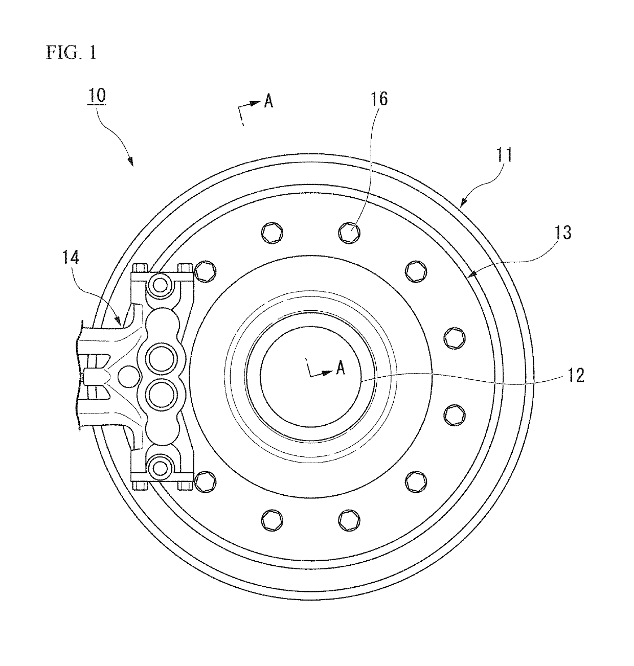
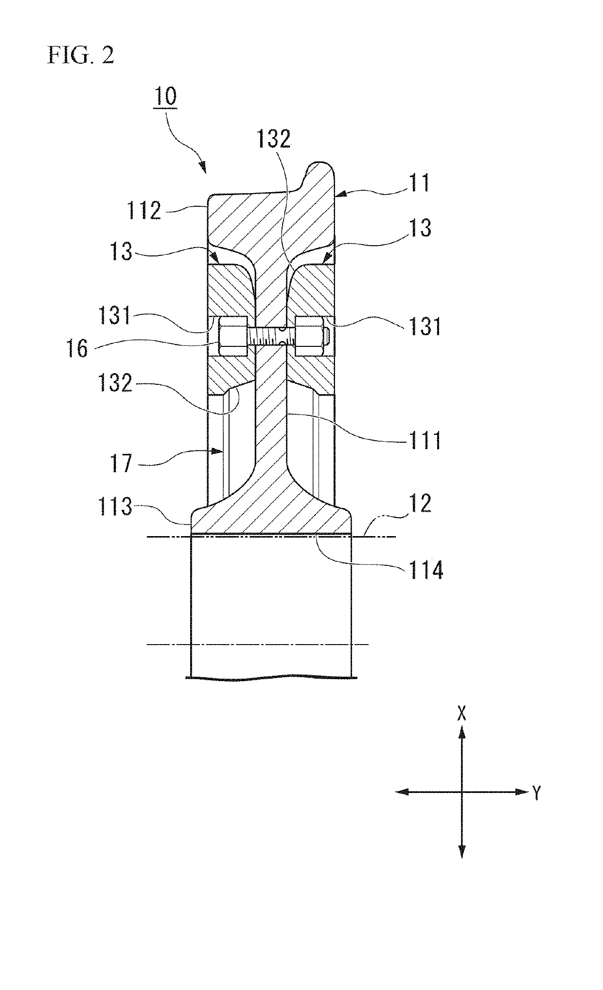
[0043]FIG. 1 is a schematic front view showing the appearance of a Shinkansen braking apparatus 10 including a brake disc 13 according to the present embodiment. In addition, FIG. 2 is a schematic cross-sectional view showing an A-A line cross-section in FIG. 1.

[0044]As shown in FIG. 1, the Shinkansen braking apparatus 10 includes a substantially round wheel 11 (rotary body), an axle 12 inserted into the wheel 11, a brake disc 13 attached to the end surface of the wheel 11, and a brake pad 14 disposed close to the brake disc 13.

[0045]As shown in FIGS. 1 and 2, the wheel 11 includes a flat plate part 111 having a constant thickness in an axial direction Y of the wheel 11, a rim part 112 which is provided at the outer edge part of the flat plate part 111 in a radial direction X of the wheel 11 and has a thickness in the axial direction Y thicker than that of the flat...


PUM

PropertyMeasurementUnit
thicknessaaaaaaaaaa
thicknessaaaaaaaaaa
grain sizeaaaaaaaaaa

Abstract

A brake disc of the present invention is a brake disc that stops the rotation of an axle when a brake pad is pressed on a surface of the brake disc, including a disc main body that is attached to a rotary body integrally rotating with the axle; and a plurality of build-up layers laminated on a surface of the disc main body, in which the build-up layers are laminated on the surface of the disc main body by means of laser metal deposition welding.

Description

TECHNICAL FIELD OF THE INVENTION[0001]The present invention relates to a brake disc and a manufacturing method thereof.[0002]Priority is claimed on Japanese Patent Application No. 2013-191081, filed on Sep. 13, 2013, the content of which is incorporated herein by reference.RELATED ART[0003]In a wheel or an axle of a railroad vehicle such as the Shinkansen, a brake disc is provided in order to obtain a braking force by pressing a brake pad thereon. Here, the brake disc has a problem of being cracked or distorted due to an influence of heat generated during braking. Therefore, a brake disc is proposed in which the surface of a disc main body of the brake disc is coated with a material having excellent heat-resisting properties, whereby cracking or distortion generated due to brake heat can be suppressed.[0004]For example, in a brake disc disclosed in Patent Document 1, first, a blast treatment is carried out on the surface of the disc main body. That is, particles made of an inorganic...

Claims


Application Information

Patent Timeline
Patent Type & Authority Patents(United States)
IPC IPC(8): F16D65/12B23K26/14B61H5/00F16D69/02B22F3/105B23K26/348B23K26/34B22F7/08F16D65/02B33Y10/00B33Y80/00
CPCF16D69/027B22F7/08B23K26/1476B23K26/34B23K26/348B61H5/00F16D65/124F16D65/127B22F3/1055F16D2250/0076B33Y10/00B33Y80/00F16D2065/132F16D2065/138F16D2200/0013F16D2200/0026F16D2200/0043F16D2250/0053Y02P10/25B22F10/66B22F10/322B22F10/36B22F10/366B22F10/25B22F12/20
Inventor SAGA, SHIN-ICHIKARINO, YASUSHIASABE, KAZUTAKASAKAGUCHI, ATSUSHIYONEYAMA, MIKIOTATSUMI, YOSHIHIRO
Owner RAILWAY TECH RES INST
Why Eureka
Try Eureka