
Implant for a bone joint

a bone joint and implant technology, applied in the field of implants for bone joints, can solve the problems of high failure rate of both total arthroplasty and hemiarthroplasty implants, high failure rate of implants, and predisposing to instability and osteoarthritis, so as to achieve greater degree of articulation and avoid complications and failure rates

Active Publication Date: 2019-04-23
NATIONAL UNIVERSITY OF IRELAND
View PDF16 Cites 0 Cited by
  • Summary
  • Abstract
  • Description
  • Claims
  • Application Information

AI Technical Summary

Benefits of technology

The modular implant design enhances the stability and longevity of bone joint replacements by allowing concurrent and independent articulation at two points, reducing the risk of failure and improving the distribution of forces across the joint, thereby addressing the high failure rates of existing implants.

Problems solved by technology

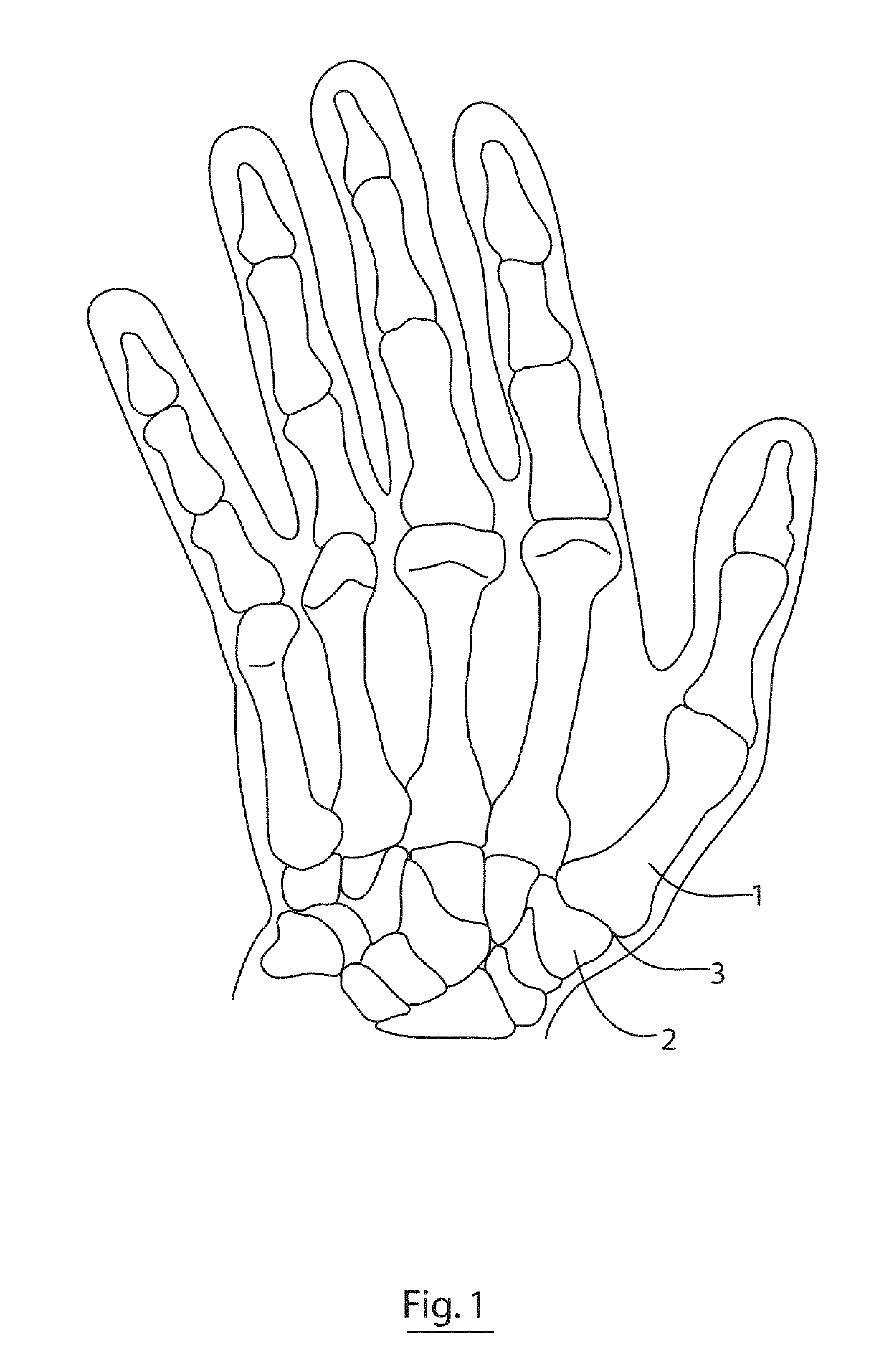
While the saddle-shaped geometry of the CMC joint is largely responsible for the wide range-of-motion and functionality of the joint, the corresponding complex biomechanics are thought to be one of the primary causes of the high failure rate of both total arthroplasty and hemiarthroplasty implants which have been designed for this joint.
This highly mobile joint may also predispose it to instability and osteoarthritis.
The other significant cause theorised as to the high failure rates of implants is the significant forces transmitted through the joint during forceful motions of the thumb, such as pinching, grasping or twisting.
As all current total arthroplasty implants for the CMC joint require the implantation of one part in the trapezium, a common failure mechanism for this type of design is subsidence or failure of the trapezium element such as the cup and socket.
The trapezium must also be surgically resected to allow placement of the cup and socket, decreasing the viable bone stock available.
Therefore, by limiting the point of rotation to one position outside the natural shifting axis of rotation, placing this point in poor quality limited bone, and then subjecting this point of stress to multiplied forces of significant amounts, it is unsurprising that failure of the ball and socket element of total arthroplasty is a common failure mechanism.
These designs have had limited success clinically, with no statistically significant difference in implant survival over total arthroplasties (Kurkhaug Y, Lie S A, Havelin L I, Hove L M, Hallan G. The results of 479 carpometacarpal joint replacements reported in the Norwegian Arthroplasty Register.
This has caused stem loosening and implant failures (Naidu S H, Kulkami N, Saunders M, Titanium Basal Joint Arthroplasty: A Finite Element Analysis and Clinical Study, The Journal of Hand Surgery.
This compromises the integrity of the trapezium bone.
As any device implanted in this joint would be expected to be under physiological compressive forces of significant amounts, this dynamic reconfiguration would be impossible to achieve to a degree that would provide any meaningful biomechanical or clinical impact.

Method used


Image

  • Implant for a bone joint
  • Implant for a bone joint
  • Implant for a bone joint

Examples


Embodiment Construction

[0088]All publications, patents, patent applications and other references mentioned herein are hereby incorporated by reference in their entireties for all purposes as if each individual publication, patent or patent application were specifically and individually indicated to be incorporated by reference and the content thereof recited in full.

Definitions and General Preferences

[0089]Where used herein and unless specifically indicated otherwise, the following terms are intended to have the following meanings in addition to any broader (or narrower) meanings the terms might enjoy in the art:

[0090]Unless otherwise required by context, the use herein of the singular is to be read to include the plural and vice versa. The term “a” or “an” used in relation to an entity is to be read to refer to one or more of that entity. As such, the terms “a” (or “an”), “one or more,” and “at least one” are used interchangeably herein.

[0091]As used herein, the term “comprise,” or variations thereof suc...


PUM


Abstract

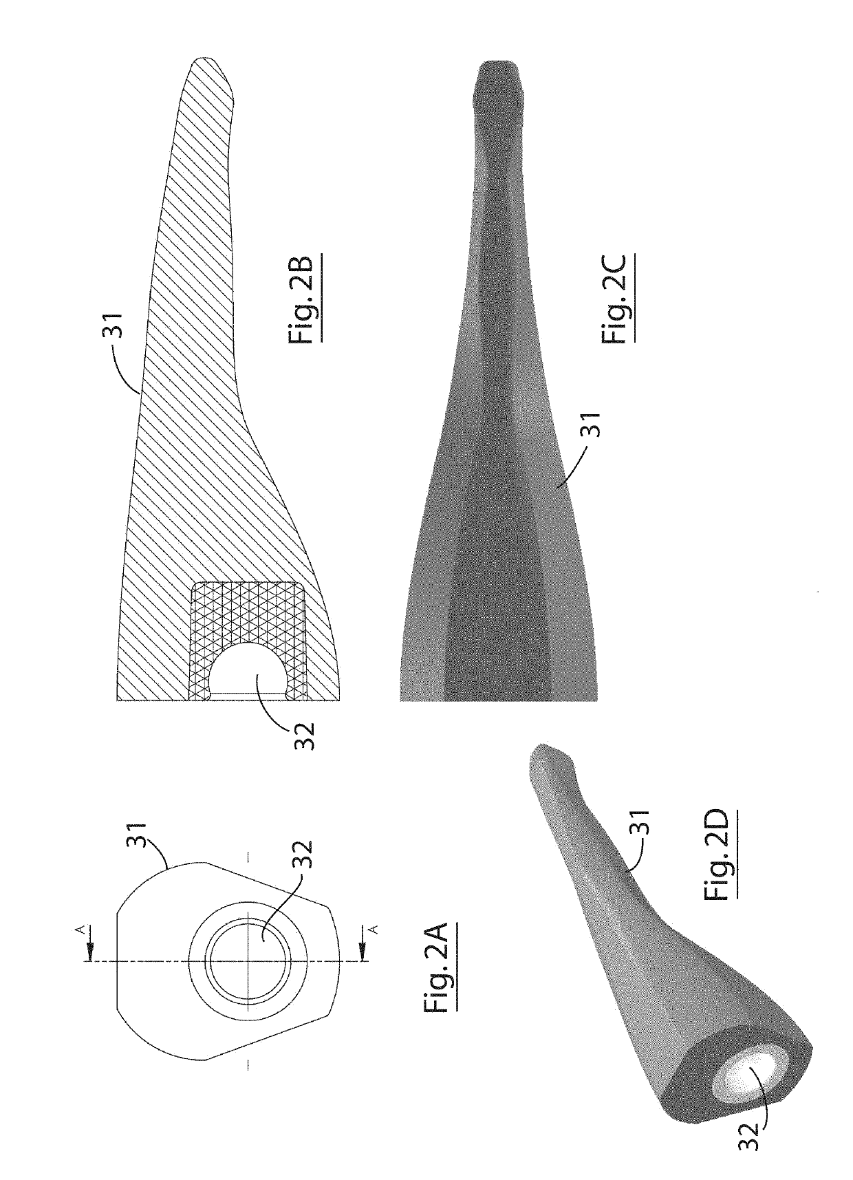
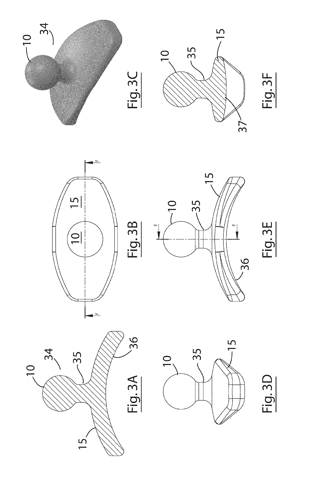
An implant (30) for a mammalian bone joint (3) for spacing a first bone (2) of the joint from a second bone (1) of the joint while allowing translational movement of the second bone in relation to the first bone is described. The implant comprises (a) a distal part (31) configured for intramedullary engagement with an end of the second bone, (b) a proximal part (34) having a platform (15) configured for non-engaging abutment of an end of the first bone and translational movement thereon, and (c) an articulating coupling (10, 16) provided between the distal and proximal ends allowing controlled articulation of the first and second bones. The bone-abutting platform is shaped to conform to and translate upon the end of the first bone. A kit for assembly to form the implant of the invention, and the use of the implant to treat osteoarthritis in a bone joint, are also described.

Description

CROSS REFERENCE TO RELATED APPLICATIONS[0001]This application claims priority to European Patent Application No. 16155090.0, filed on Feb. 10, 2016, the contents of which is incorporated herein by reference in its entirety.TECHNICAL FIELD[0002]The invention relates to an implant for a bone joint, especially a carpometacarpal joint. In particular, the invention relates to a modular implant for a bone joint. The invention also relates to a kit of parts that can be assembled to form the bone joint implant of the invention. The invention also relates to a method of treating osteoarthritis or performing a hemi-arthroplasty by implanting a bone joint implant of the invention into a bone joint for the purpose of spacing articulating bones.BACKGROUND TO THE INVENTION[0003]Joint replacements may be generally divided into two designs—total arthroplasty and hemiarthroplasty. Total arthroplasty designs generally replace both sides of the joint, for example, a total hip replacement is made up of...

Claims


Application Information

Patent Timeline
Patent Type & Authority Patents(United States)
IPC IPC(8): A61F2/42A61F2/30
CPCA61F2/4241A61F2002/3038A61F2002/3055A61F2002/30065A61F2002/30301A61F2002/30378A61F2002/30604A61F2002/30649A61F2002/4253A61F2002/4258A61F2310/00017A61F2310/00023A61F2310/00029A61F2310/00059A61F2310/00089A61F2310/00161A61F2310/00173A61F2/30A61F2002/30331
Inventor CLARKE, GERRYBOLAND, BRENDANBRUZZI, MARKLADD, AMY L.WEISS, ARNOLD-PETER C.STOCKMANS, FILIP
Owner NATIONAL UNIVERSITY OF IRELAND
Learn More