
Compact multifunctional system for imaging spectroscopy

a multi-functional, compact technology, applied in the field of imaging spectroscopy, can solve the problems of compromising resolution, compromising spatial resolution, difficult acquisition of 3d hyperspectral imaging data, etc., and achieve the effect of increasing the spectral reconstruction quality of an imaged scen

Active Publication Date: 2019-04-30
ECOLE POLYTECHNIQUE FEDERALE DE LAUSANNE (EPFL)
View PDF8 Cites 6 Cited by
  • Summary
  • Abstract
  • Description
  • Claims
  • Application Information

AI Technical Summary

Benefits of technology

This approach enables the creation of compact, lightweight, and cost-effective spectral imaging systems that achieve higher resolution spectral data cubes with significantly reduced data acquisition, facilitating applications in agriculture and environmental monitoring while lowering production and operational costs.

Problems solved by technology

The acquisition of 3D hyperspectral imaging data is difficult because of the two-dimensional nature of the imaging sensors.
Due to the spectral dispersion, spatial resolution must be compromised.
Frame, or snapshot, spectral cameras acquire the entire data cube without scanning, severely compromising resolution.
For color images, the method has been suggested in [5], but the practical implementation has been limited by the low information gain and high computational cost with respect to classical demosaicing.
These experiments, however, failed to produce the results needed for a practical snapshot spectral camera which requires compression ratios around 1 / 50 or more.
The color imaging methods described in [5] cannot be directly applied to 2D spectral sampling-based imaging for a plurality of reasons:Correct pixel-wise spectral reconstruction poses a series of new challenges such as optimal spectral distribution of filters, or higher order filter response cancellation.Color filter arrays do not provide sufficient spectral separationFor hyperspectral image reconstruction, the algorithms need to reconstruct a significantly larger set of data from less than 5% of its size, as opposed to 33% subsampling rate of color imaging.
Due to the very stringent requirements of spectral imaging, a spectral filter array is much more difficult to produce than the color arrays used in commercial color cameras.
Color cameras generally employ pigment-based filters whose spectral transmission bandwidth is too wide and irregular for the radiometric measurements of spectral imaging.
The number of different filters that can be produced in a pigment-based color filter array is also limited by the number of pigments used.
The cost of a color filter array thus greatly increases with the increase in the number of different filters.
While their properties make them an obvious choice for imaging spectroscopy, until recently, interferometric filters were not feasible to create at the size of a single pixel.
One of the main disadvantages of interferometric filters is their second and higher order transmissions.
In most cases, the higher order transmissions are undesired effects and need to be nullified.

Method used


Image

  • Compact multifunctional system for imaging spectroscopy
  • Compact multifunctional system for imaging spectroscopy
  • Compact multifunctional system for imaging spectroscopy

Examples


Embodiment Construction

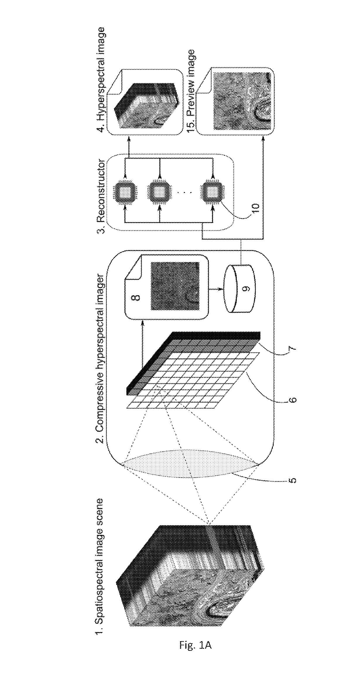
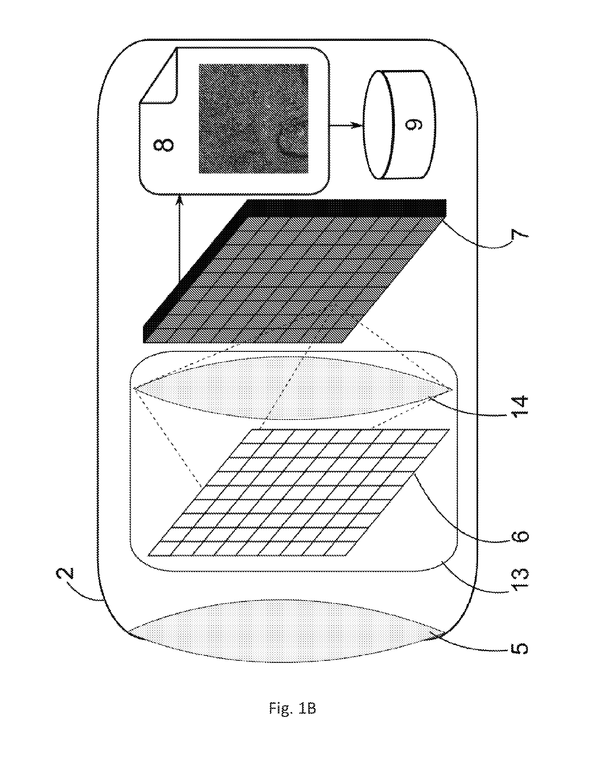
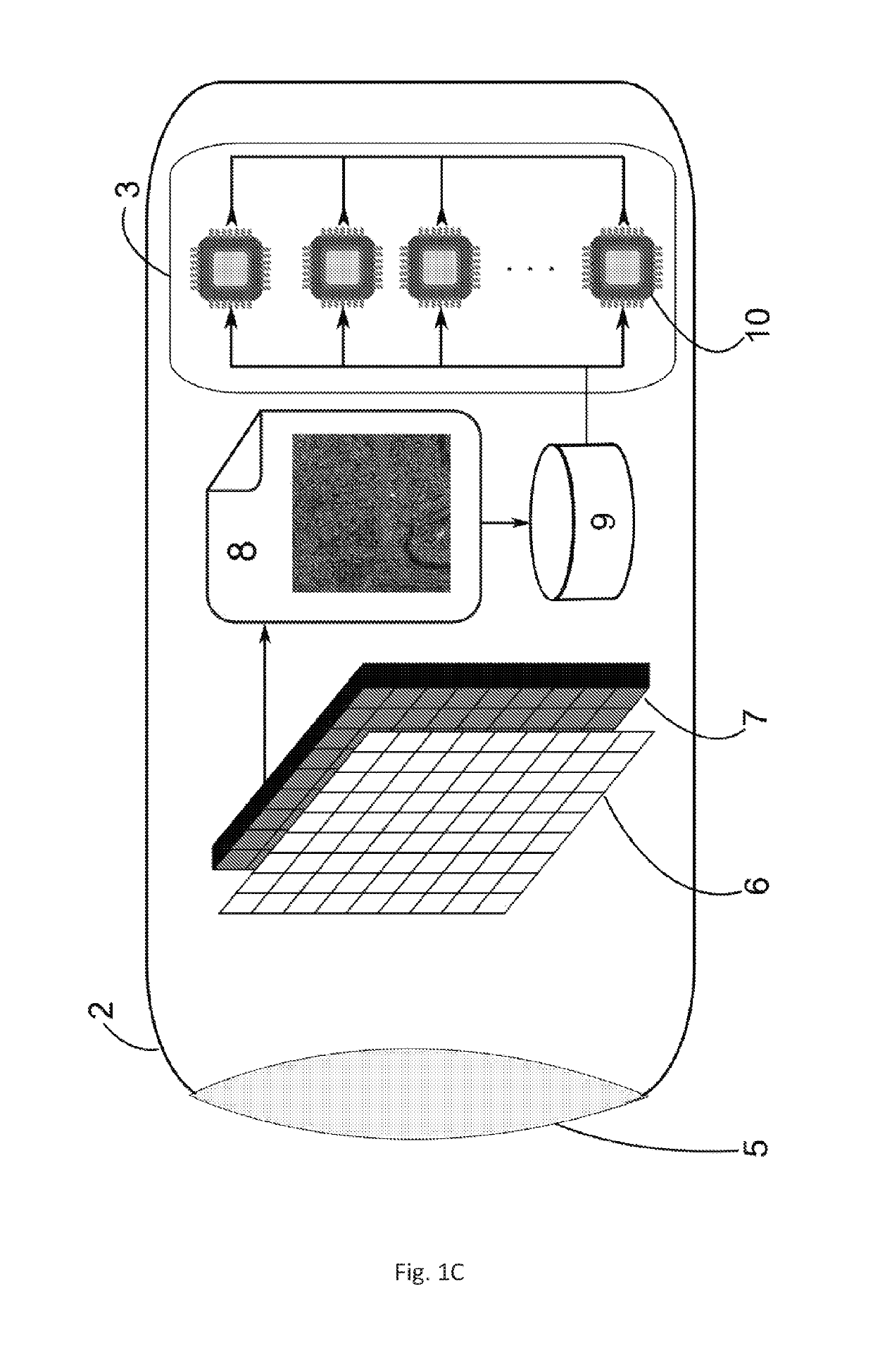
[0059]In this section, we outline the advantages of the presented solution with respect to prior art and subsequently focus on the technical details pertaining to three major aspects of the invention, namely:[0060]1. the camera design and functionality;[0061]2. the spectral filter array design; and[0062]3. the reconstructor embodiments and preferred implementation.

[0063]The present invention improves upon prior art in multiple ways. With respect to spatial or spectral scanning spectral imaging systems, the present invention overcomes the need to scan, sampling the imaged scene simultaneously while providing similar resolution. Due to the extremely short optical path of the present invention, a much smaller and lighter spectral image acquisition system can be built than those requiring spectrally dispersive elements. The reduced complexity of the optical and mechanical parts also significantly lowers the production cost when compared to spectral imaging systems with dispersive elemen...


PUM

PropertyMeasurementUnit
central wavelengthsaaaaaaaaaa

Abstract

A method for obtaining spectral imaging data comprises at least the steps of receiving a sample set of data generated by sampling a spectral property of an image of an object in a spatial basis, wherein the sampling of the spectral property of the image of the object comprises providing a Spectral Filter Array (SFA) by arranging a plurality of SFA elements together to form a surface; configuring each SFA element of the plurality of SFA elements to filter one or more spectral bandwidths centered each at specific wavelengths corresponding to that SFA element, whereby all of the plurality of SFA elements taken together cover a determined spectral range; and setting the specific wavelengths of each SFA element of the plurality of SFA elements on the surface such to obtain a uniform and aperiodic spatial distribution of all of the plurality of SFA elements across the surface. The sampling of the spectral property of the image of the object further comprises providing an image sensor configured to record at each pixel the light filtered by one of the plurality of SFA elements or a subset of the plurality of SFA elements thereby producing one intensity value of light filtered by the one of the plurality of elements or the subset of the plurality of SFA elements per pixel; forming the image of the object on the SFA through a lens or group of lenses; and recording for all of the pixels of the image sensor the spectrally filtered intensity values thereby obtaining a 2-dimensional array of the intensity values corresponding to the image of the object. The method for obtaining spectral imaging data further comprises the step of reconstructing a full 3 dimensional spectral data cube of the imaged object from the sampled 2-dimensional array.

Description

CROSS REFERENCE TO RELATED APPLICATIONS[0001]The present application is a U.S. national stage application of PCT / IB2015 / 055614 filed on Jul. 24, 2015 designating the United States, and claims foreign priority to International patent application PCT / IB2014 / 063366 filed on Jul. 24, 2014, the contents of both documents being herewith incorporated by reference in their entirety.TECHNICAL FIELD OF INVENTION[0002]The invention relates to the field of imaging spectroscopy, and more precisely hyperspectral imaging. More specifically, the invention comprises a compressive spectral image acquisition and reconstruction system.BACKGROUND OF INVENTION[0003]Imaging Spectroscopy[0004]Imaging spectroscopy is a digital sensing process in which a scene is optically sampled in two spatial dimensions and in one spectral dimension, producing a three dimensional data cube. Spectral images contain significantly larger amount of spectral information than color photography, typically comprising tens or hund...

Claims


Application Information

Patent Timeline
Patent Type & Authority Patents(United States)
IPC IPC(8): G01J3/02H04N13/214G06T17/05G06K9/00G01J3/28G01N21/31G06V20/13
CPCG01N21/31G01J3/027G01J3/0229G01J3/2823G06K9/00657G06T17/05H04N13/214G06K9/0063G06K2009/00644G01J2003/2826G06V20/194G06V20/13G06V20/188
Inventor AKHTMAN, YOSEFCONSTANTIN, DRAGOS
Owner ECOLE POLYTECHNIQUE FEDERALE DE LAUSANNE (EPFL)
Learn More