Synchronous rectifier gate driver with active clamp

Active Publication Date: 2019-04-30
STMICROELECTRONICS SRL
View PDF14 Cites 6 Cited by
  • Summary
  • Abstract
  • Description
  • Claims
  • Application Information

AI Technical Summary

Benefits of technology

The present patent describes a resonant converter with a synchronous rectifier driver that reduces voltage spikes and improves efficiency. The driver uses an active clamp made of a transistor, Zener diode, and resistor to achieve this. The clamp minimizes power loss by sinking current to the output terminal of the converter. This embodiment also utilizes a Darlington Mosfet configuration to increase intervention time of the active clamp.

Problems solved by technology

These voltage spikes may be caused for a variety of reasons, such as current inversion due to a delayed turn-off of the rectifier and the resonant converter operating above resonance and the transistors' body diode recovery time.

Method used


Image

  • Synchronous rectifier gate driver with active clamp
  • Synchronous rectifier gate driver with active clamp
  • Synchronous rectifier gate driver with active clamp

Examples


first embodiment

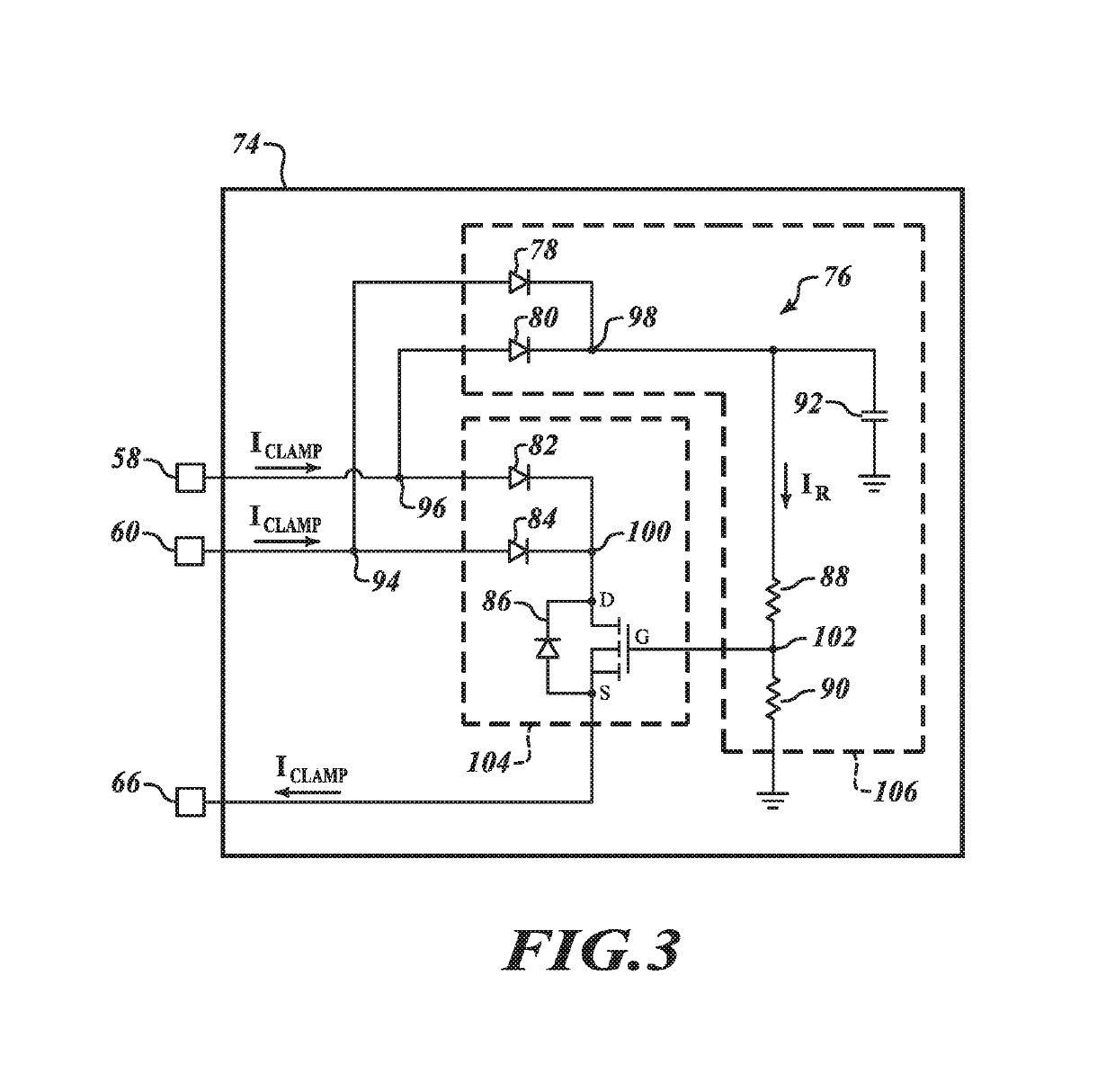
[0054]FIG. 3 shows a detailed diagram of the active clamp 74, disclosed herein. In the embodiment shown in FIG. 3, the active clamp 74 includes circuitry 76. The circuitry 76 includes a first diode 78, a second diode 80, a third diode 82, a fourth diode 84, a transistor 86, a first resistor 88, a second resistor 90, and a capacitor 92. The first input 58 of the synchronous rectifier driver 56 is electrically coupled to a node 96 of the circuitry 76, the second input 60 of the synchronous rectifier driver 56 is electrically coupled to a node 94 of the circuitry 76, and the third output 66 of the synchronous rectifier driver 56 is electrically coupled to a source of the transistor 86.

[0055]The first diode 78 is electrically coupled between the node 94 and a node 98, the second diode 80 is electrically coupled between the node 96 and the node 98, the third diode 82 is electrically coupled between the node 96 and a node 100, and the fourth diode 84 is electrically coupled between the n...

third embodiment

[0069]For applications in which the voltages at the drains of the transistor 44, 46 (VDVS44, VDVS46) have very fast commutation times, the clamping module 104 of the active clamp 74 may be activated dynamically using a driving module. FIG. 5 shows a detailed diagram of the active clamp, disclosed herein. In the embodiment shown in FIG. 5, the active clamp 74 includes circuitry 116. Similar to the circuitry 76 shown in FIG. 3, the circuitry 116, specifically the clamping module 104, includes the third diode 82, the fourth diode 84, and the transistor 86. However, in contrast to the circuitry 76, the threshold setting module 106 is replaced with a driving module 118.

[0070]The driving module 118 includes a diode 120, a capacitor 124, and a driver 126. The gate of the transistor 86 is electrically coupled to a node 128. The diode 120 is electrically coupled between the node 128 and the third output 66 of the synchronous rectifier driver 56. The capacitor 124 is electrically coupled bet...

fourth embodiment

[0080]In the fourth embodiment, the maximum voltage at the drain of the transistor 44 may be calculated using equation (18):

VDVS44=Vext+VTH132+VD82  (18)

where VDVS44 is the voltage at the drain of the transistor 44, Vext is the external voltage applied at the third input 134, VTH132 is a voltage threshold of the transistor 132, and VD82 is the voltage drop on the third diode 82. Similarly, the maximum voltage at the drain of the transistor 46 may be calculated using equation (19):

VDVS46=Vext+VTH132+VD84  (19)

where VDVS46 is the voltage at the drain of the transistor 46, Vext is the external voltage applied at the third input 134, VTH132 is a voltage threshold of the transistor 132, and VD84 is the voltage drop on the fourth diode 84.

[0081]In one embodiment, the external voltage Vext is set to be twice the output voltage VOUT. The external voltage Vext may be calculated using equation (20):

Vext=2·VOUT  (20)

In this embodiment, the maximum voltage at the drain of the transistor 44 may ...


PUM


Abstract

Various embodiments provide a resonant converter that includes a synchronous rectifier driver. The synchronous rectifier driver reduces voltage spikes on drains of transistors within the resonant converter by placing an active clamp between the drains of the transistors and an output terminal of the resonant converter. The active clamp reduces the voltage spikes by sinking current at the drains of the transistors to an output capacitor. By sinking the current to the output terminal, power loss is minimized and efficiency of the resonant converter is improved.

Description

BACKGROUNDTechnical Field[0001]The present disclosure is directed to a synchronous rectifier driver for resonant converters and other topologies.Description of the Related Art[0002]In general, resonant converters convert an input voltage having a first voltage level to an output voltage having a second voltage level, and regulate the output voltage for a load. Resonant converters are typically used for powering electronic devices, such as displays for televisions, computers, and mobile devices. Resonant converters are highly efficient and have become increasingly popular for applications with power constraints, such as battery operated devices.[0003]Many resonant converters include a rectifier that utilizes a plurality of transistors to convert an alternating current (AC) signal to a direct current (DC) signal. Voltage spikes are often generated on drains of the transistors and may sometimes damage the resonant converter. These voltage spikes may be caused for a variety of reasons, ...

Claims


Application Information

Patent Timeline
IPC IPC(8): H02M3/335H02M7/217H02M1/08H02M1/34H02M1/00
CPCH02M1/083H02M7/217H02M3/335H02M2001/0058H02M3/33592H02M3/33569H02M1/34H02M1/088H02M3/3376H02M1/0058H02M1/342
Inventor IORIO, ALBERTOFORESTA, MAURIZIO
Owner STMICROELECTRONICS SRL
Why Eureka
Try Eureka