
Device intended for implementing an anodization treatment and anodization treatment

a technology of anodizing treatment and anodizing treatment, which is applied in the direction of coatings, electrolysis components, electrolysis processes, etc., can solve the problems of high electricity consumption, several limits, and the present micro arc anodizing technique in a large vessel, and achieve the effect of saving energy consumption, superfluous expensive steps of installing resists or masks, and saving in terms

Active Publication Date: 2019-06-25
SAFRAN HELICOPTER ENGINES +1
View PDF13 Cites 2 Cited by
  • Summary
  • Abstract
  • Description
  • Claims
  • Application Information

AI Technical Summary

Benefits of technology

The invention is a device that allows for anodizing treatment to be carried out in a concentrated manner, reducing energy consumption and allowing for larger parts to be treated without the need for immersion. The device uses a treatment chamber of the same size as the surface to be treated, eliminating the need for additional tank space and reducing the amount of electrolyte needed. The device also allows for better control over the heat produced during treatment, resulting in coatings that meet specific requirements. Overall, the invention provides a simple and cost-effective solution for anodizing treatment.

Problems solved by technology

Nevertheless, making a coating by the present micro arc anodizing technique in a large vessel (vessel having a volume of about 0.5 cubic meters (m3)) can present several limits.
Firstly, that technique can involve using a generator delivering high value bipolar currents, given the large surface area of the part(s) for treatment, which can lead to high levels of electricity consumption.
Furthermore, it can be difficult to obtain a coating by micro arc anodizing on a part of large area because of the high currents needed for anodizing.
Furthermore, since micro arc anodizing treatment consumes a large amount of energy, the temperature of the electrolyte in prior art bath treatments can be difficult to control.
The desire to regulate the temperature of the bath can lead to using an installation that is relatively complex, thereby significantly increasing the cost of performing the treatment.
Another disadvantage of prior art micro arc anodizing methods is that it can be difficult to measure reliably certain parameters of the electrolyte in the bath while the anodizing treatment is being performed.
Nevertheless, putting resists into place can be relatively expensive and can make the organization of fabrication significantly more complex.
Furthermore, the masking step may be difficult to perform and can thus make the treatment significantly more expensive.

Method used


Image

  • Device intended for implementing an anodization treatment and anodization treatment
  • Device intended for implementing an anodization treatment and anodization treatment

Examples


Embodiment Construction

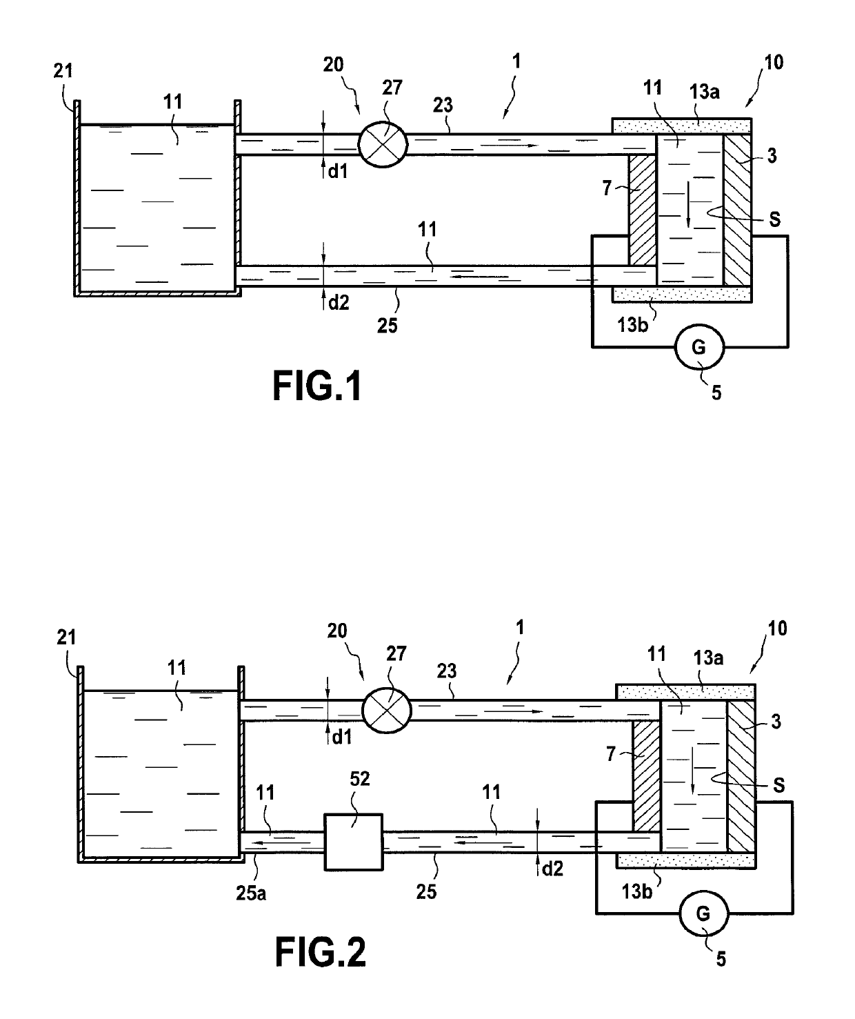
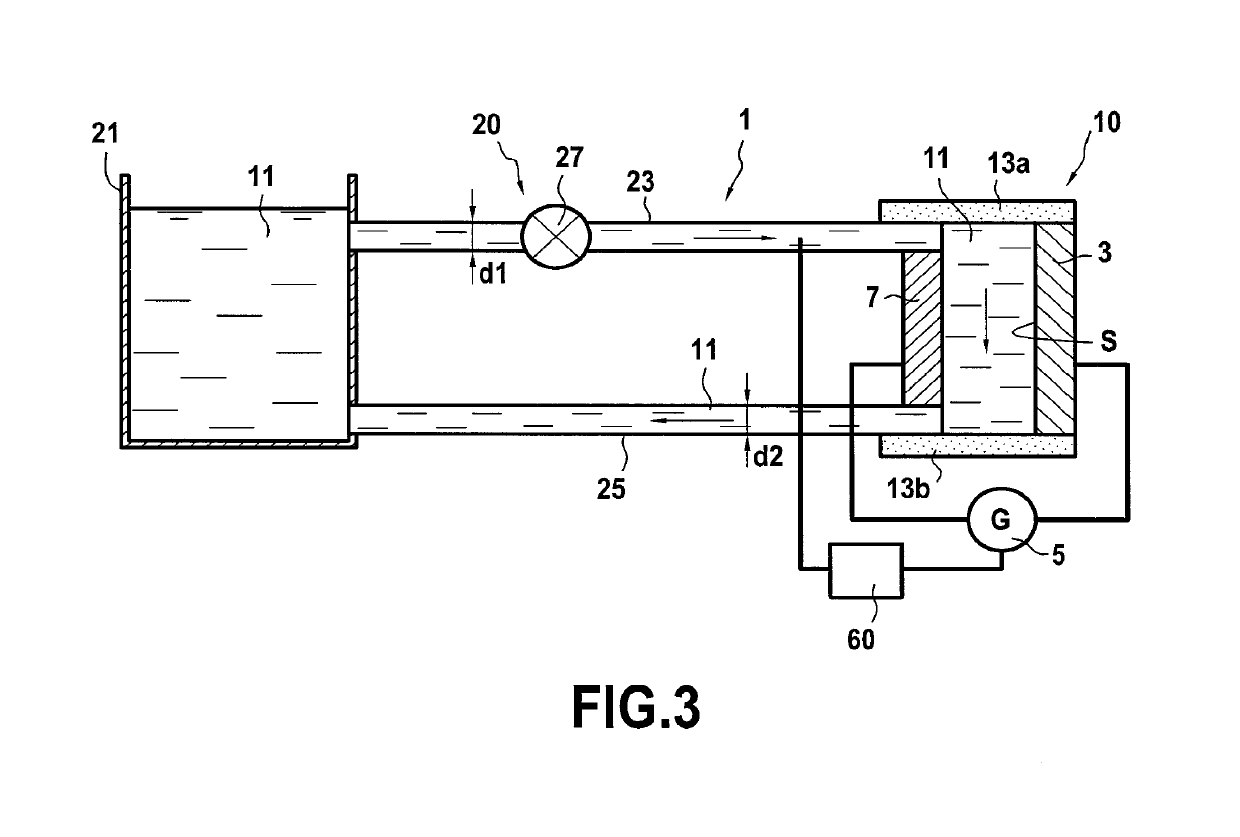
[0048]FIG. 1 shows an embodiment of a device 1 of the invention. The device 1 comprises the part to be treated 3 and a generator 5. The part to be treated 3 is for being subjected to anodizing treatment, preferably micro arc oxidation. The generator 5 serves to perform this anodizing. As shown, a first terminal of the generator 5 is electrically connected to the part 3, and a second terminal of the generator 5 is electrically connected to a counter-electrode 7 situated facing the part 3. The generator 5 is advantageously configured to apply alternating current (AC).

[0049]The counter-electrode 7 is preferably made of stainless steel. More generally, it is possible to use any electrically-conductive material for the counter-electrode 7 providing it is compatible with performing anodizing treatment.

[0050]The device 1 has a treatment chamber 10 in which the anodizing treatment is to be performed, the part 3 to be treated constituting a first wall of the treatment chamber 10 and the coun...


PUM

PropertyMeasurementUnit
volumeaaaaaaaaaa
lengthaaaaaaaaaa
lengthaaaaaaaaaa

Abstract

A device for performing anodizing treatment on a part, the device including a treatment chamber including a part for anodizing together with a counter-electrode situated facing the part to be treated, the part to be treated constituting a first wall of the treatment chamber; a generator, a first terminal of the generator being electrically connected to the part to be treated and a second terminal of the generator being electrically connected to the counter-electrode; and a system for storing and circulating an electrolyte, the system including a storage vessel, different from the treatment chamber, for containing the electrolyte; and a circuit for circulating the electrolyte in order to enable the electrolyte to flow between the storage vessel and the treatment chamber.

Description

BACKGROUND OF THE INVENTION[0001]The invention relates to devices for performing anodizing treatment, preferably micro arc anodizing treatment, and it also relates to associated methods.[0002]It is known to treat alloys based on magnesium, aluminum, or titanium by micro arc anodizing. That technique serves to make layers with very low porosity and of hardness that is much greater than the hardness of an amorphous oxide that could be obtained by conventional anodizing such as sulfuric anodic oxidation (SAO), chromic anodic oxidation (CAO), or phosphoric anodic oxidation (PAO). Specifically, in micro arc anodizing treatments, the oxide layer on the surface of the part is formed as a result of generating microelectric discharges leading to the formation of micro arcs that have the ability to raise the temperature of the surface of the part very locally so as to crystallize the amorphous oxide that forms during the anodizing step. In micro arc anodizing treatment, the parts may be immer...

Claims


Application Information

Patent Timeline
Patent Type & Authority Patents(United States)
IPC IPC(8): C25B15/08C25D11/00C25D21/18C25D21/06C25D17/12C25D17/02C25D11/02C25D21/12C25B15/02C25B9/00
CPCC25D21/12C25D11/005C25D11/026C25D21/18C25D17/12C25D21/06C25D17/02C25D11/02
Inventor GURT SANTANACH, JULIENVIOLA, ALAIN
Owner SAFRAN HELICOPTER ENGINES
Learn More