Compression coil spring and method for producing same

a compression coil spring and coil spring technology, applied in the direction of furnaces, heat treatment equipment, manufacturing tools, etc., can solve the problems of dimensional accuracy, surface roughness formation, premature breakage, etc., and achieve the effect of high durability and generation of residual stress

Active Publication Date: 2019-07-23
NHK SPRING CO LTD
View PDF42 Cites 0 Cited by
  • Summary
  • Abstract
  • Description
  • Claims
  • Application Information

AI Technical Summary

Benefits of technology

[0016]In view of above-mentioned circumstances, an object of the present invention is to provide a compression coil spring and a method for producing same in which generation of residual stress by coiling processing is avoided and high durability is obtained using an inexpensive wire material by giving appropriate compressive residual stress distribution to wire material after forming.
[0017]The inventors have researched about fatigue resistance of a coil spring. As a result, they have found that although residual stress that is generated by processing can be reduced to some extent by controlling of steel components by adding expensive elements, which improves tempering softening resistance, or by controlling annealing conditions thereafter; however, it is fundamentally difficult to completely solve the residual stress problem by the processing while maintaining steel strength required for fatigue resistance and settling resistance against load stress. Then, they have also found that effects of shotpeening and setting that are performed subsequently can be effectively obtained, by producing a coil spring while restraining generation of residual stress during processing by performing coiling processing while heating the coil spring wire material in the austenite region.
[0018]Furthermore, in the heating step to the austenite region, a shorter heating time may be brought into restraining of coarsening of prior austenite crystal particle diameter (hereinafter referred to as “crystal particle diameter”) or may be brought into miniaturization. Furthermore, this crystal particle diameter has a close relationship with fatigue resistance, and miniaturization of crystal particles is effective for improving fatigue resistance. Therefore, by hot-processing using the wire material heated in a short time, residual stress caused by processing can be prevented from being generated, and thus, it becomes possible to produce a spring having superior fatigue resistance.

Problems solved by technology

Here, in a case in which Rz is more than 20 μm, concave parts of the surface roughness may become sources at which stress concentrates, cracking may be generated and spread from the concave parts as origin points, and this may result in premature breakage.
Furthermore, this surface roughness is formed by friction with tools during coiling, and by shotpeening treatment.
There was a problem in dimensional accuracy in Comparative Example 3 that was produced by the production process D. For example, the standard deviation of coil diameter that was evaluated for fifty coil springs after they were tempered, was 0.072 mm, and this could not satisfy the standard deviation of 0.05 mm or less which is required for valve springs or clutch torsion springs.
This is because large processing strain remained in the coil spring after the cold forming, and the processing strain was not distributed uniformly in one coil spring, and in addition, there was variation in processing strain among multiple coil springs.
By heating at an austenite region and quenching this coil spring, thereby resulting in non-uniform deformation, which is accompanied by loosening of processing strain and transformation stress, that is, there was variation in the shapes.

Method used


Image

  • Compression coil spring and method for producing same
  • Compression coil spring and method for producing same

Examples


examples

Evaluation of Coiling Property

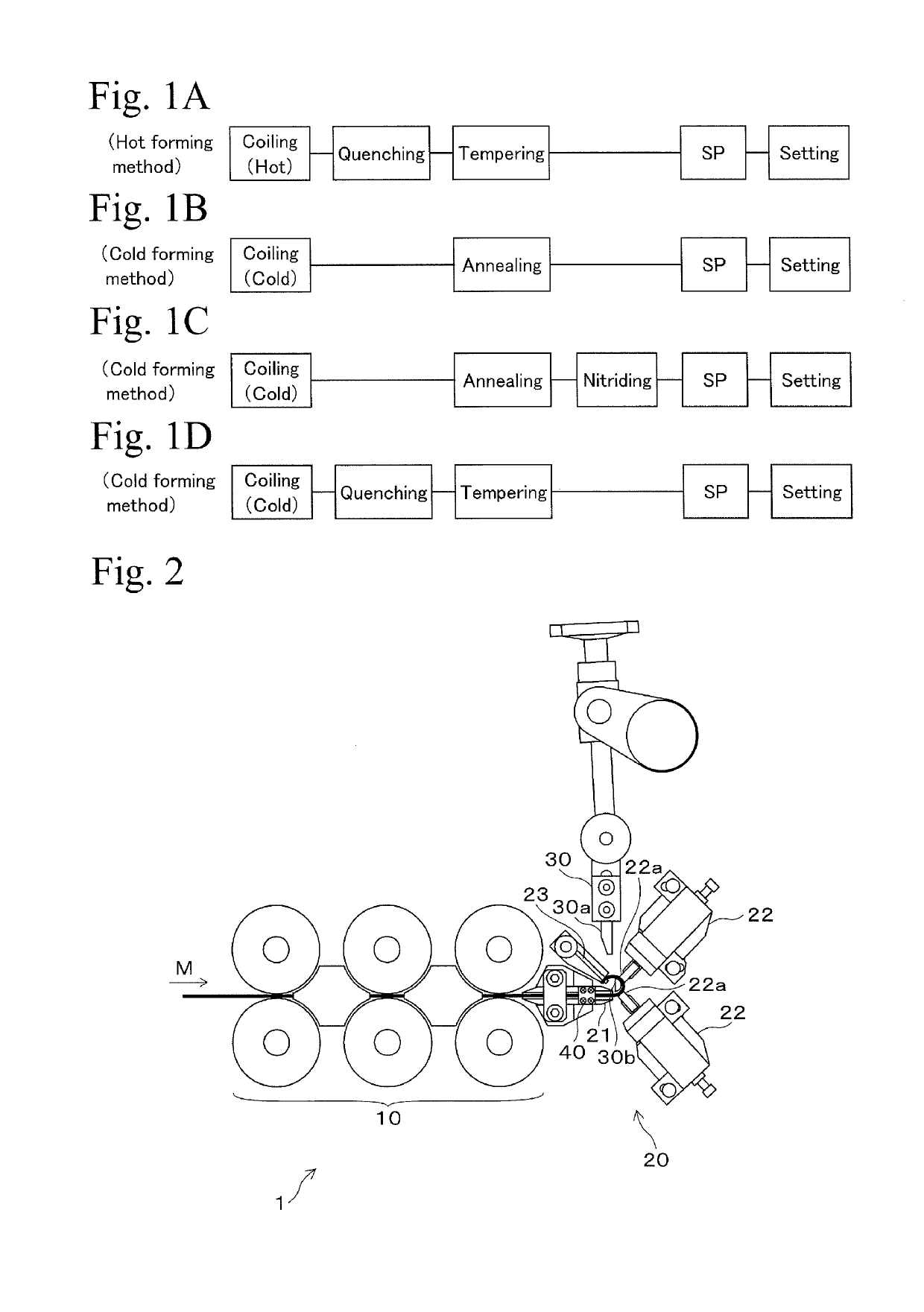
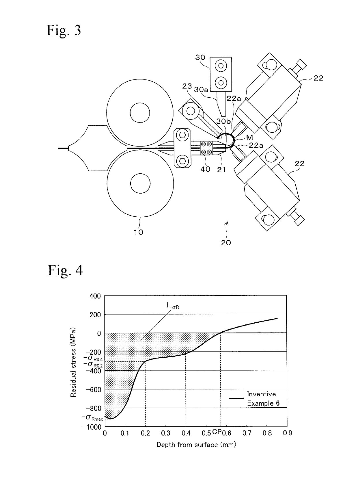
[0062]First, coiling property was evaluated by using a coiling machine (see FIGS. 2 and 3) having a high frequency heating coil. Oil tempered wires, each of them having a wire diameter of 1.0 to 10.0 mm and having chemical component shown in Table 1, were prepared, and they were coiled while heating the wire material at 900° C. by the coiling machine. Coiling was performed under combined conditions of wire diameter d and spring index D / d shown in Table 2.

[0063]

TABLE 1(wt %)CSiMnCr0.51 to 0.591.20 to 1.600.50 to 0.800.50 to 0.80

[0064]

TABLE 2Samplesd (mm)D / dCoiling propertyExample 11.06.0IVExample 21.26.0IIIExample 31.56.0IExample 42.06.0IExample 53.06.0IExample 64.02.5IVExample 74.03.0IExample 84.06.0IExample 94.08.0IExample 105.06.0IExample 117.06.0IExample 129.06.0IExample 1310.06.0II

[0065]Evaluation results of coiling property are also shown in Table 2. In Table 2, “I” means that the approximately circular coil spring could be produced without being a...


PUM

PropertyMeasurementUnit
diameteraaaaaaaaaa
surface roughness Rzaaaaaaaaaa
Vickers hardnessaaaaaaaaaa

Abstract

A compression coil spring having high durability can be provided by using an inexpensive wire material. The present invention provides a compression coil spring formed by using a steel wire material, the steel wire material made of C: 0.45 to 0.85 mass %, Si: 0.15 to 2.5 mass %, Mn: 0.3 to 1.0 mass %, Fe and inevitable impurities as a remainder, and a circle-equivalent diameter of 1.5 to 9.0 mm, wherein hardness of a freely selected cross-section of the wire material is 570 to 700 HV, and at an inner diameter side of the coil spring, unloaded compressive residual stress at a depth of 0.2 mm from a surface in an approximate maximal main stress direction in a case in which compressive load is loaded on the spring is 200 MPa or more, and unloaded compressive residual stress at a depth of 0.4 mm from surface is 100 MPa or more.

Description

TECHNICAL FIELD[0001]The present invention relates to a compression coil spring for use in an engine and clutch of a vehicle, for example, and in particular, relates to a compression coil spring which exhibits superior fatigue resistance even in environments of high stress, and relates to a method for producing the same.BACKGROUND ART[0002]In recent years, it has been progressively required to reduce the fuel consumption of vehicles in view of environmental problems, and reduction in size and weight of parts for vehicles has been also severely required more than ever. To satisfy the requirements for reduction in size and weight, research on strengthening of materials and surface strengthening by a surface treatment have been actively performed in the field of compression coil spring parts such as a valve spring used in an engine or a clutch torsion spring used in a clutch, for example. As a result, fatigue resistance and settling resistance, which are important properties in a coil ...

Claims


Application Information

Patent Timeline
Patent Type & Authority Patents(United States)
IPC IPC(8): C21D9/02C22C38/04C22C38/02C22C38/18C22C38/24F16F1/02B21F35/00C22C38/34C21D8/06C21D7/06C22C38/46F16F1/06B24C1/10
CPCF16F1/021B21F35/00B24C1/10C21D7/06C21D8/065C21D9/02C22C38/04C22C38/18C22C38/24C22C38/34C22C38/46F16F1/06C22C38/02C21D2211/008
Inventor IKAI, KAZUYASHIRAISHI, TOHRUONO, YUICHIROONO, YOSHIKI
Owner NHK SPRING CO LTD
Why Eureka
Try Eureka