Ambient light sensor

a light sensor and ambient technology, applied in the field of ambient light sensors, can solve the problems of not being able to reduce take a relatively long sensing time, etc., and achieve the effect of reducing the size of the electronic device, long sensing time, and reducing the sensing tim

Active Publication Date: 2019-09-10
ANPEC ELECTRONICS CORPORATION
View PDF4 Cites 8 Cited by
  • Summary
  • Abstract
  • Description
  • Claims
  • Application Information

AI Technical Summary

Benefits of technology

[0007]As described above, in comparison with a conventional electronic device including only a small number of optoelectronic components, it takes a relatively long sensing time when a light intensity of an ambient light source is low. In order to reduce the sensing time, a large number of photoelectric components are required to be disposed in an improved conventional ambient light sensor. Those photoelectric components occupy a considerable space of an integrated circuit in an electronic device, so that a size of the electronic device cannot be reduced. Therefore, the present disclosure provides the ambient light sensor, in which the variable capacitor and the pulse generator are additionally configured for the other circuit components of the ambient light sensor. As a result, the ambient light sensor can accurately sense the light intensity of the ambient light source in a short time, under the condition that only the small number of (two) photoelectric components are disposed in the ambient light sensor to save circuit component configuration costs and reduce an occupied space. Accordingly, the electronic device can adjust a display screen to have a more desirable brightness according to a sensing result of the ambient light sensor.

Problems solved by technology

As described above, in comparison with a conventional electronic device including only a small number of optoelectronic components, it takes a relatively long sensing time when a light intensity of an ambient light source is low.
Those photoelectric components occupy a considerable space of an integrated circuit in an electronic device, so that a size of the electronic device cannot be reduced.

Method used


Image

  • Ambient light sensor
  • Ambient light sensor
  • Ambient light sensor

Examples


first embodiment

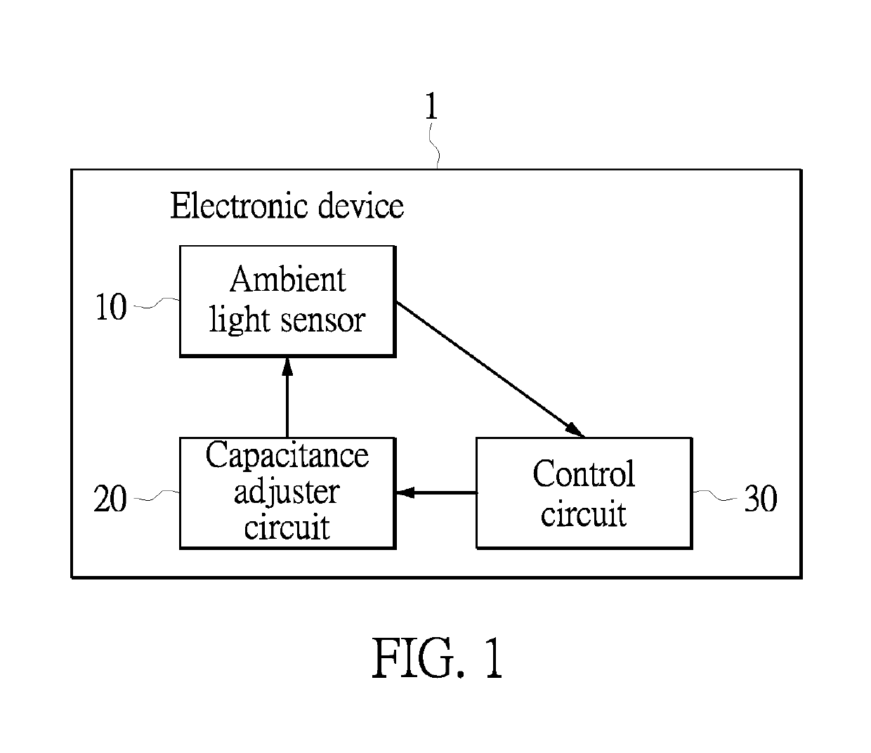
[0020]Reference is made to FIG. 1, which is a block diagram of internal components of an electronic device to which an ambient light sensor is applied according to the present disclosure. As shown in FIG. 1, in the embodiment, the ambient light sensor 10 may be applied for an electronic device 1 such as a mobile device. The ambient light sensor 10 is disposed at a position corresponding to a display screen of the electronic device 1. The ambient light sensor 10 is configured to sense a light intensity of an ambient light source illuminating on the display screen of the electronic device 1, such as an ambient light intensity in an indoor environment or an outdoor environment. It should be noted that a control circuit 30 of the electronic device 1 may instruct a capacitance adjuster circuit 20 to adjust a sensing time and accuracy of the ambient light sensor 10. The control circuit 30 of the electronic device 1 may adjust brightness of the display screen of the electronic device 1 acc...

second embodiment

[0045]Reference is made to FIG. 4, which is a circuit layout diagram of an ambient light sensor applied for an electronic device according to the present disclosure. As shown in FIG. 4, in the embodiment, the ambient light sensor 10 includes the operational amplifier 100, the comparator 200, the logic circuit 300, a pulse accumulator circuit 410, the pulse generator circuit 500, a pulse storage circuit 610, the photoelectric components PD1 and PD2, a constant capacitor C2, the current mirror circuit M1 and the switch components S1 and S2.

[0046]Differences between the first embodiment and the second embodiment are described below. First, the capacitor C1 of the first embodiment is the variable capacitor, but the capacitor C2 of the second embodiment is the constant capacitor or a called non-variable capacitor. In practice, the constant capacitor C2 of the second embodiment may be replaced with a variable capacitor. In the second embodiment, the pulse generator circuit 500 is disposed...

third embodiment

[0054]Reference is further made to FIG. 6, which is a waveform diagram of an amplified error signal outputted by an operational amplifier, a comparison signal outputted by a comparator, a logic signal outputted by a logic circuit, the number of counts accumulated by a pulse accumulator circuit and an enable signal inputted to a pulse storage circuit of the ambient light sensor according to the present disclosure. As shown in FIG. 6 from top to bottom, waveforms belong to the reference voltage source VREF for the operational amplifier 100 and the comparator 200, an amplified error signal EAO3 outputted by the operational amplifier 100, a comparison signal CMP3 outputted by the comparator 200, a logic signal LOG3 outputted by the logic circuit 300, the number of counts CON3 outputted by the pulse accumulator circuit 410, and an enable signal IT_EN inputted to the pulse storage circuit 610 respectively.

[0055]When the voltage of the amplified error signal EAO3 is increased to a voltage ...


PUM


Abstract

An ambient light sensor is provided, which includes a photoelectric component, a variable capacitor, an operational amplifier, a comparator, a pulse generator circuit and a pulse accumulator circuit. The photoelectric component converts light energy into a photocurrent. The variable capacitor is connected between a first input terminal and an output terminal of the operational amplifier. A capacitance of the variable capacitor is adjusted according to the photocurrent. The operational amplifier outputs an amplified error signal based on a difference between an input voltage at its first input terminal and a reference voltage at its second input terminal. The comparator compares the amplified error signal with the reference voltage to output a comparison signal. The pulse generator circuit outputs a pulse signal based on the comparison signal. The accumulator circuit accumulates the number of counts that the input voltage is increased to a voltage larger than the reference voltage.

Description

CROSS-REFERENCE TO RELATED PATENT APPLICATION[0001]This application claims the benefit of priority to Taiwan Patent Application No. 107136536, filed on Oct. 17, 2018. The entire content of the above identified application is incorporated herein by reference.[0002]Some references, which may include patents, patent applications and various publications, may be cited and discussed in the description of this disclosure. The citation and / or discussion of such references is provided merely to clarify the description of the present disclosure and is not an admission that any such reference is “prior art” to the disclosure described herein. All references cited and discussed in this specification are incorporated herein by reference in their entireties and to the same extent as if each reference was individually incorporated by reference.FIELD OF THE DISCLOSURE[0003]The present disclosure provides an ambient light sensor, and in particular to an ambient light sensor which can accurately sen...

Claims


Application Information

Patent Timeline
Patent Type & Authority Patents(United States)
IPC IPC(8): H05B37/02H05B33/08H05B44/00
CPCH05B37/0272H05B37/0227H05B37/0218H05B33/0851H05B33/0818G01J1/46H05B45/10H05B47/105H05B47/11Y02B20/40
Inventor CHEN, CHIH-NINGSU, CHIH-HENG
Owner ANPEC ELECTRONICS CORPORATION
Why Eureka
Try Eureka