Spine correction apparatus

a technology for adjusting apparatus and spine, applied in the field of spine adjusting apparatus, can solve the problems of affecting patients' quality of life, easy complications of surgery, and impaired pulmonary function and cardiac disease, and achieve the effect of improving the effect of adjusting surgery and reducing patient suffering

Active Publication Date: 2019-10-15
CHANG GUNG MEMORIAL HOSPITAL
View PDF8 Cites 2 Cited by
  • Summary
  • Abstract
  • Description
  • Claims
  • Application Information

AI Technical Summary

Benefits of technology

[0006]For addressing the foregoing need, the present invention provides a spine correction apparatus that delivers effective correction of scoliosis and sufficient spinal support, and eliminates the need of repeated surgeries for progressive adjustment, thereby significantly improving the effect of correction surgery and reducing patients' suffering.
[0011]In the disclosed spine correction apparatus, a buffer space is provided between the first ring member and the second rod, or between the second ring member and the first rod. The buffer space receives therein a spring element that pushes the first rod's first zone against the second rod's second zone. The spring element may be a compression spring, an extension spring, a torsion spring, a flat spring, a disk spring, and so on, in which a flat spring is preferable. In addition, the way that the first ring member fixed to the first rod and the second ring member fixed to the second rod are not limited, and may be any fixing ways known in the art, such as rivets, bolts, screws, tenon-and-mortise works, and so on. Preferably, bolts and screws are used for this purpose, such as slotted plain bolts, hexagon socket bolts, tapping screw, and set screw, to fix the first ring member and the second ring member to the first rod and the second rod firmly and respectively. Alternatively, the first rod and the first ring member can be integrally formed or integrated as one piece as well as the second rod and the second ring member. This helps to reduce the risk of failure or lower manufacturing costs. In addition, the first ring member and the second ring member may each have more than one through-hole. In other words, the first ring member may further have another first through-hole in addition to the first through-hole, and the second ring member may further have another second through-hole in addition to the second through-hole.
[0015]With the disclosed spine correction kit, a correction apparatus adapted to a patient's individual scoliosis conditions can be assembled, and then the first rod and the second rod are fixed to the patient's vertebral body where correction is required. Afterward, with the growth of the patient's spine, the correction apparatus extends or contracts in length. Preferably, it extends at the concave side and contracts at the convex side of the patient's spine. The disclosed spine correction apparatus having a simple structure composed of a few parts is easy to be operated and has extensive applications. The kit can be well customized into correction apparatuses depending on patients' individual needs. As compared to the conventional devices, the disclosure is unlikely to fail due to mechanical fatigue, and thus has a longer service life, thereby eliminating the need of repeated surgeries and complications, and having good clinical feasibility.

Problems solved by technology

But the spinal fusion surgery is not appropriate for the children whose spine is still growing, that will restrict their spinal growth, and lead to the impairment of pulmonary function and cardiac disease.
Patients receiving this treatment suffer from repeated surgeries is easy to have complications such as wound infection as well as the significant impact on their quality of life and psychological stresses.
Unfortunately, these known apparatuses are assembly complex and thus bulky.
While there are some apparatuses designed to be compact, they defectively have frangible axes.
However, their corrective effects are limited.

Method used


Image

  • Spine correction apparatus
  • Spine correction apparatus
  • Spine correction apparatus

Examples


embodiment 1 spine

Correction Kit

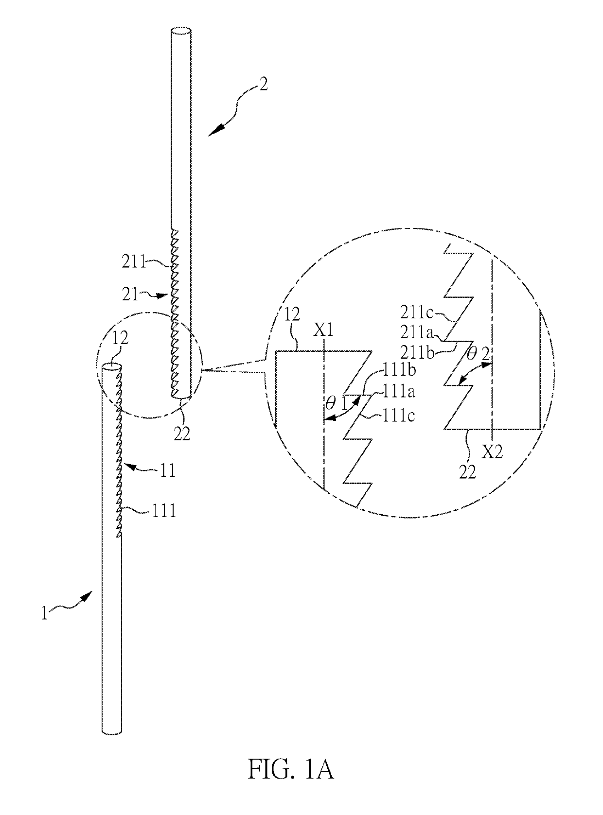
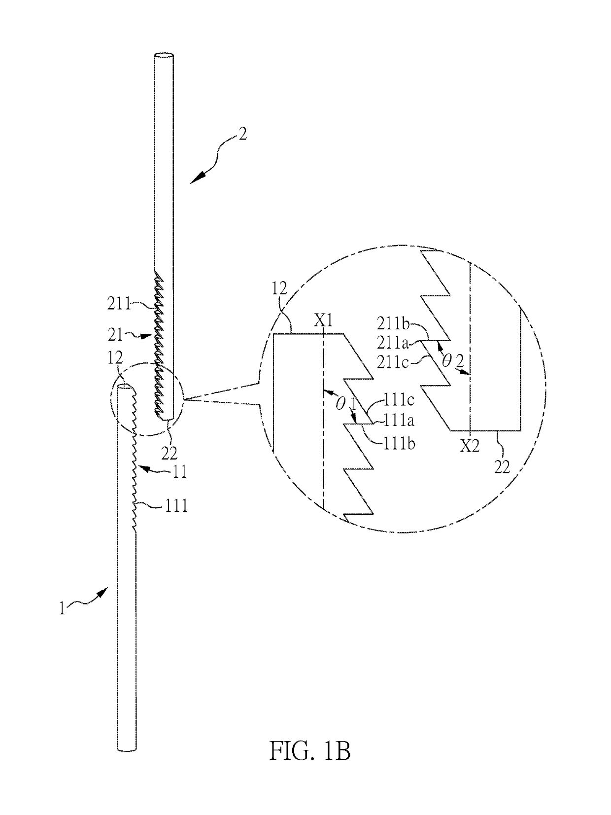
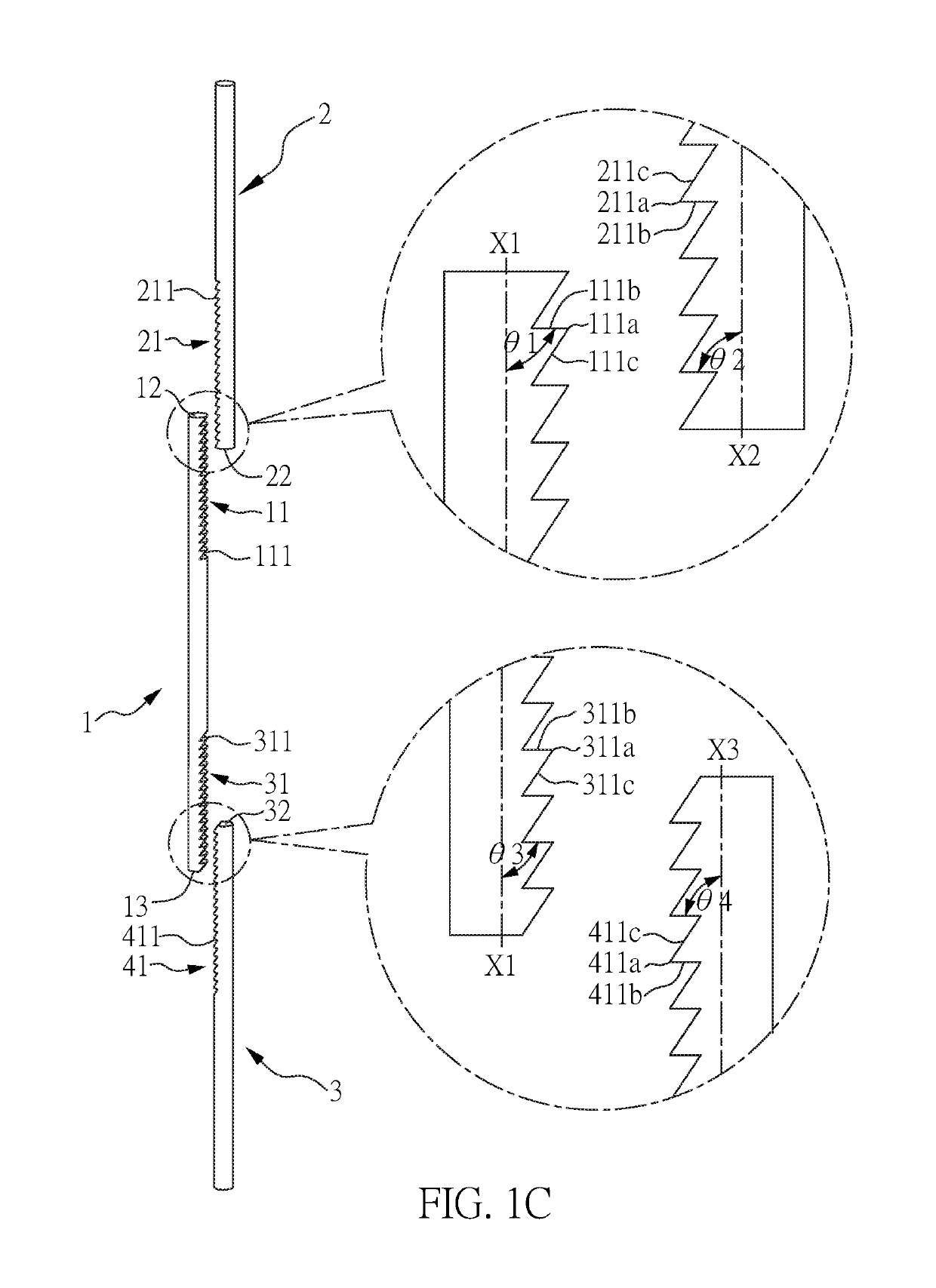
[0030]According to the present invention, a spine correction kit at least comprises: a first rod, a second rod, a first ring member, and a second ring member. Please refer to FIG. 1A through 1E for rods included in the spine correction kit. FIGS. 1A, 1B, 1D, and 1E show the first rod and the second rod, while FIG. 1C show the first rod, the second rod, and the third rod. A detailed description thereto is given below.

[0031]Referring to FIG. 1A, 1B, the first rod 1 has a first zone 11 in which plural first raised teeth 111 are provided. Each of the first raised teeth 111 has a first top edge 111a, a first lateral 111b, and a second lateral 111c. The first lateral 111b is connected to the second lateral111c by means of the first top edge 111a. The first lateral 111b and a major axis direction X1 of the first rod 1 include a first included angle θ1. The second rod 2 has a second zone 21 in which plural second raised teeth 211 are provided. Each of the second raised teeth 2...

embodiment 2 spine

Correction Apparatus

[0037]Type 1

[0038]First, the first rod 1 of FIG. 1A has its top surface 12 facing the first through-hole of the first ring member 64 and the second through-hole of the second ring member 65 (i.e. placed in the first direction as shown in FIG. 6A), and passes through the second through-hole of the second ring member 65 and the first through-hole of the first ring member 64 successively (the configuration of the first ring member 64 and the second ring member 65 are shown in FIG. 4A). A set screw 71 is used to fix the first ring member 64 to the first rod 1, and that is close to the top surface 12. Then, the second rod 2 of FIG. 1A has its bottom surface 22 facing the first through-hole of the first ring member 64 and the second through-hole of the second ring member 65 (i.e. placed in the second direction as shown in FIG. 6A), and passes through the first through-hole of the first ring member 64 and the second through-hole of the second ring member 65 successively...


PUM


Abstract

A spine correction apparatus is disclosed, comprising: a first rod member having a first zone; a second rod member having a second zone; a first ring member having a first through-hole; and a second ring member having a second through-hole; wherein the first zone contacts the second zone, the first rod member and the second rod member are inserted into the first through-hole and the second through-hole, the first through-hole is fixed to the first rod member, and the second through-hole is fixed to the second rod member. The spine correction apparatus lowers the requirement for repeated surgeries and achieves the purpose of self-correction.

Description

CROSS REFERENCE TO RELATED APPLICATION[0001]This application claims the benefits of the Taiwan Patent Application Serial Number 105108084, filed on Mar. 16, 2016, the subject matter of which is incorporated herein by reference.BACKGROUND OF THE INVENTION1. Field of the Invention[0002]The present invention relates to a spine correction apparatus, and more particularly to a spine correction apparatus for correction of scoliosis.2. Description of Related Art[0003]Scoliosis refers to an abnormal spinal deformity. The corrective spinal surgery needs to be performed for the patients who ineffectively respond to conservative treatment like bracing. Spinal fusion surgery is the most effective treatment to correct and control the Cobb angle of the deformity spine. But the spinal fusion surgery is not appropriate for the children whose spine is still growing, that will restrict their spinal growth, and lead to the impairment of pulmonary function and cardiac disease. The growing rod system is...

Claims


Application Information

Patent Timeline
Patent Type & Authority Patents(United States)
IPC IPC(8): A61B17/70A61B17/00
CPCA61B17/701A61B17/7014A61B17/705A61B2017/00477
Inventor LAI, PO-LIANGWANG, JAW-LINCHEN, ZONG-XING
Owner CHANG GUNG MEMORIAL HOSPITAL
Why Eureka
Try Eureka