Visually assisted entry of a Veress needle with a tapered videoscope for microlaparoscopy

a technology of tapered videoscope and veress needle, which is applied in the field of visual assistance of veress needle with tapered videoscope for microlaparoscopy, can solve the problems of inability to avoid inadvertent entry into an organ, injuring abdominal organs and major blood vessels, and blind placement of veress needle and then blind placement of the port with inserted trocar a much more risky technique, so as to increase the safety of the puncture and reduce the pain of patien

Active Publication Date: 2019-11-05
ENABLE
View PDF31 Cites 4 Cited by
  • Summary
  • Abstract
  • Description
  • Claims
  • Application Information

AI Technical Summary

Benefits of technology

[0024]Commercially available, miniature, digital camera sensors, with high number of imaging pixels that can be used to construct small OD videoscopes are available and are becoming smaller as time progresses (without losing resolution). A videoscope is an imaging device that utilizes a digital imaging sensor at its distal tip, including an imaging lens, and illumination is provided either via optical fiber transmission or by having LEDs at its distal tip as well. A micro-objective lens is also necessary to be positioned distal to the digital imaging sensor to image the space distal to it onto the active area of the sensor. If optical fibers are used for illumination they need to run along the length of the videoscope from its proximal end all the way to the distal end. If LED's are used for illumination, the OD of the distal tip of the videoscope is larger than when fibers are used for illumination, as the LEDs need to be packaged and heat-sinked appropriately for proper use. This action by default increases the overall cross-sectional space needed when LEDs are utilized for illumination in an imaging scope. The image is carried to the proximal end of the scope via electrical cables attached to the back end of the digital sensor for further processing and display.
[0027]For a given miniature digital imaging sensor the tapered design will allow the maximum number of pixel sensor (highest resolution available) to be used to construct a small-enough tip videoscope that can fit down the smallest possible gas-insufflation sheath of a standard Veress needle, while providing a large enough annular space between the tapered-down shaft of the scope and insufflation sheath of the needle for simultaneous gas insufflation. Thus, allowing for normal gas insufflation through the Veress needle without causing pressure alarms while the visualization scope resides inside the Veress needle, and while keeping the overall size of the Veress needle as small as possible and preferably the same as any standard size miniature Veress needle.
[0028]Another object of this invention is to show how a standard Veress needle can be modified so that it can be used along with the proposed tapered videoscope. It is also the object of this invention to show how such tapered, miniature, high-resolution videoscope can be used as a stylet (the visualization stylet) and inserted through the modified Veress needle to visually assist the entry of the Veress needle through tissue, during puncture of the tissue, as well as insufflation, and beyond without having to be removed; thus greatly increasing the safety of the puncture as well as the procedure that follows after the primary puncture, since the body cavity reached can be under constant direct visualization throughout.
[0029]Finally another object of this invention is to use such combination of instruments for regular laparoscopic surgeries or diagnostic procedures. The small incision and tissue trauma due to the miniature OD of the Veress needle proposed here translates to less pain for the patient, faster recovery times, and less expensive procedures compared to regular laparoscopic procedures or regular surgery.SUMMARY OF THE INVENTION
[0030]The current invention describes the design of a novel videoscope with fiber illumination (visualization stylet) to be used through any standard existing size Veress needle and assist in the direct visualization of the passage of the Veress needle through tissue, during insufflation, and post insufflation during the whole length of the laparoscopic procedure. Such a tool can address the problems that have been identified in the literature with the first blind puncture of a Veress needle to achieve pneumoperitoneum during laparoscopic surgery, and worse yet with the more dangerous second (initially blind) puncture of the much larger trocar for insertion of a large-size laparoscope and illumination into the abdomen after insufflation of the abdominal cavity (see for example “Entry complications in laparoscopic Surgery” J. Gynecol Endosc. Surg. 1(1): 4-11, 2009). Furthermore, since the proposed visualization stylet can remain in place without impeding the function of the Veress needle, it can also be used as a quick and efficient diagnostic laparoscopic tool that requires only one small puncture through the abdomen. The utility of microlaparoscopy (one that could be performed in an outpatient setting, possibly under local anesthesia) has been identified since the 1990s (see for exampleobgyn.net / laparoscopy / microlaparoscopy and “Microlaparoscopy using an optical Veress needle inserted at Palmer's point,” Gynecological Endoscopy 8, 115-116 (1999)).

Problems solved by technology

The problem with such procedures, however, is the fact that the body cavity is entered blindly on two separate occasions: first, through the introduction of the Veress needle; and second, through the introduction of the laparoscopic port with inserted trocar, which can and on occasion does injure abdominal organs and major blood vessels.
In this regard, it is known that when a patient has undergone previous abdominal surgery, the abdominal contents can become adherent to the abdominal wall, making blind placement of a Veress needle and then blind placement of the port with inserted trocar a much more risky technique.
In fact, inadvertent entry into an organ cannot be avoided via use of such device, and it is only after the organ is entered, and hence damaged, that such matter can be appraised.
Moreover, the use of clear plastic has substandard optical visualization due to optical properties inherent in such material, coupled with the conical shape, such that advancement of the tip fails to provide a clear visualization as the same is advanced through tissue.
This patent teaches the use of a fiberscope for visualization which implies a constant diameter scope with poor image quality due to the small number of pixels.
More importantly viewing is limited by the inability of the viewing scope to get past the distal tip of the cutting sheath.
Furthermore visualization is not possible during entry or insufflation.
But it is still a large device that requires an equally large incision, including a large and expensive laparoscope.
Because of all of the above, such commercial devices would never be possible to accommodate outpatient, minimally invasive laparoscopies that may not require anesthesia.
Not all of the above mentioned commercial products can accommodate pneumoperitoneum with the proposed laparoscope in place.
The system offers poor optics (being a fiberoptic scope).
In addition, these expensive and very delicate instruments fracture easily given their narrow diameter and top-heavy camera end.
The poor quality of the optics in these mini laparoscopes, and their fragility (due to the coherent imaging fiber bundle construct; fiberscope) render them impractical to use.
Furthermore no teachings are made of a tapered scope design that can accommodate a high-resolution digital sensor while it can still allow insufflation through a standard small Veress needle.
Furthermore they are no teachings in this patent about a tapered visualization scope.

Method used


Image

  • Visually assisted entry of a Veress needle with a tapered videoscope for microlaparoscopy
  • Visually assisted entry of a Veress needle with a tapered videoscope for microlaparoscopy
  • Visually assisted entry of a Veress needle with a tapered videoscope for microlaparoscopy

Examples


Embodiment Construction

A. Preferred Changes to a Standard Veress Needle

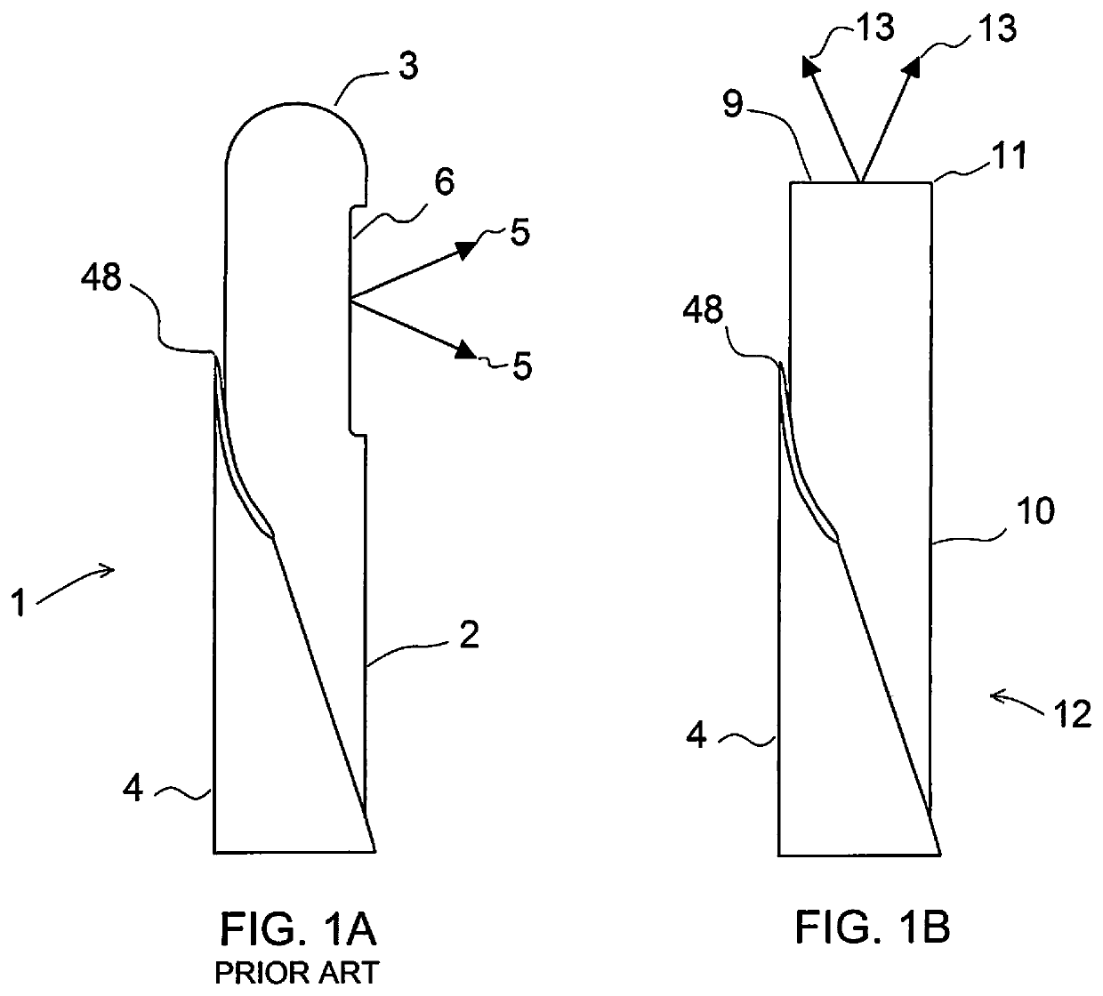
[0048]Minimal changes can be made to a standard Veress needle 1 to accommodate the functionality of this embodiment of the proposed visualization stylet. Typically the movable inner sheath 2 of the Veress needle (the spring-action blunt inner-cannula that carries the insufflation gas) has a rounded distal tip 3 with a side port 6 for the insufflation gas 5 to pass through, as shown in FIG. 1A. This longitudinal sheath 2 will also be referred to as the gas-flow sheath. The rounded distal tip 3 of this sheath helps prevent any inadvertent damage during the first abrupt puncture of the abdominal cavity with the needle 4 portion of the Veress needle, while allowing for the passage of gas 5 from the side port 6 (after puncture through the abdomen). The passage and direction of gas flow through the side port 6 is indicated by the arrows 5 in FIG. 1A; standard use of a Veress needle insufflation.

[0049]The current embodiment of the visualizati...


PUM


Abstract

A Veress needle is modified to receive a forward-looking miniature videoscope through the cannula of an insufflation tube of the Veress needle. The modified instrument enables direct viewing of progress of the instrument through tissue to the peritoneal cavity of a patient, for proper location of the needle and insufflation of the cavity via the needle. The videoscope has an elongated shaft of smaller diameter than the cannula of the insufflation tube for passage of insufflation gas with the scope in place. In another embodiment a needle is fitted with a miniature videoscope to provide the same function, with the needle's cannula serving as an insufflation tube.

Description

[0001]This application claims benefit of provisional application Ser. No. 62 / 076,417, filed Nov. 6, 2014.BACKGROUND OF THE INVENTION[0002]Laparoscopic, thoracoscopic, arthroscopic, and other endoscopic procedures are well-known surgical techniques that reduce patient recovery time due to minimal tissue damage. Generally, these surgical techniques rely upon the formation of one or more puncture wounds through which a body cavity, such as the peritoneal or the thoracic cavity, can be accessed. In laparoscopic surgery, once the peritoneal cavity has been entered, the same is insufflated with carbon dioxide gas, typically to a pressure of approximately 15 mm-20 mmHg, followed by the introduction of an endoscopic port with inserted trocar, which may either be bladed or blunt.[0003]Most surgeons initially enter the peritoneal cavity using a Veress needle which is pushed blindly through the patient's fascia and peritoneum. The peritoneal cavity is then insufflated followed by the introduct...

Claims


Application Information

Patent Timeline
Patent Type & Authority Patents(United States)
IPC IPC(8): A61B1/313A61B17/34A61B1/05A61B1/00A61B1/015A61B17/00A61B90/00
CPCA61B1/00154A61B1/015A61B1/05A61B17/3474A61B1/00177A61B90/361A61B2017/00004A61B2017/00473A61B17/3403A61B17/3496A61B1/273A61B17/3478
Inventor SAVVOURAS, ODYSSEFS ATH.PAPADEMETRIOU, STEPHANOSKOTSEROGLOU, THEOFILOSHAUG, ULRICH R.
Owner ENABLE
Why Eureka
Try Eureka