Eureka AIR delivers breakthrough ideas for toughest innovation challenges, trusted by R&D personnel around the world.

Composite materials having embedded metal ropes for increased damping capacity and methods of manufacturing same

a technology of composite materials and metal ropes, which is applied in the field of composite materials having embedded metal ropes for increasing damping capacity and manufacturing same, can solve the problems of macroscopic scale failure, failure of net sections of parts, and failure of composite materials on both microscopic or macroscopic scales, so as to increase the damping capacity of components formed, increase the strength of individual wires, and increase the effect of friction damping

Active Publication Date: 2019-12-03
FORD GLOBAL TECH LLC
View PDF13 Cites 0 Cited by
  • Summary
  • Abstract
  • Description
  • Claims
  • Application Information

AI Technical Summary

Benefits of technology

[0009]The disclosed inventive concept provides a method and system for increasing damping capacity in components formed from composite materials by utilizing dry friction between individual wires of an embedded rope. The rope is embedded into the component during the casting process. The individual wires allow inter-wire friction to occur during part vibration. The strength of the individual wires is preferably higher than that of the surrounding composite material, thereby increasing the amount of friction damping that the inter-wire friction provides to the damped composite component.
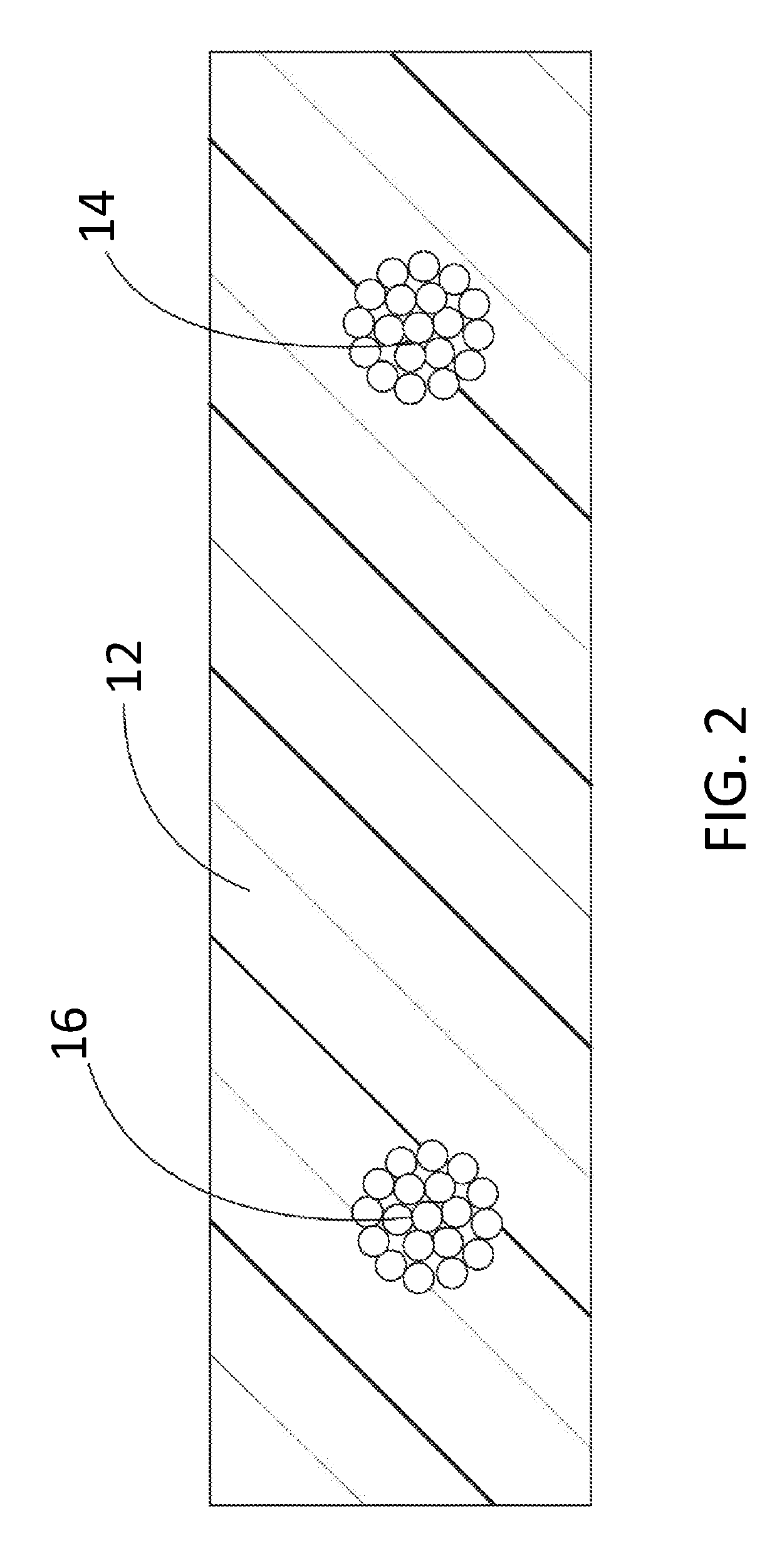
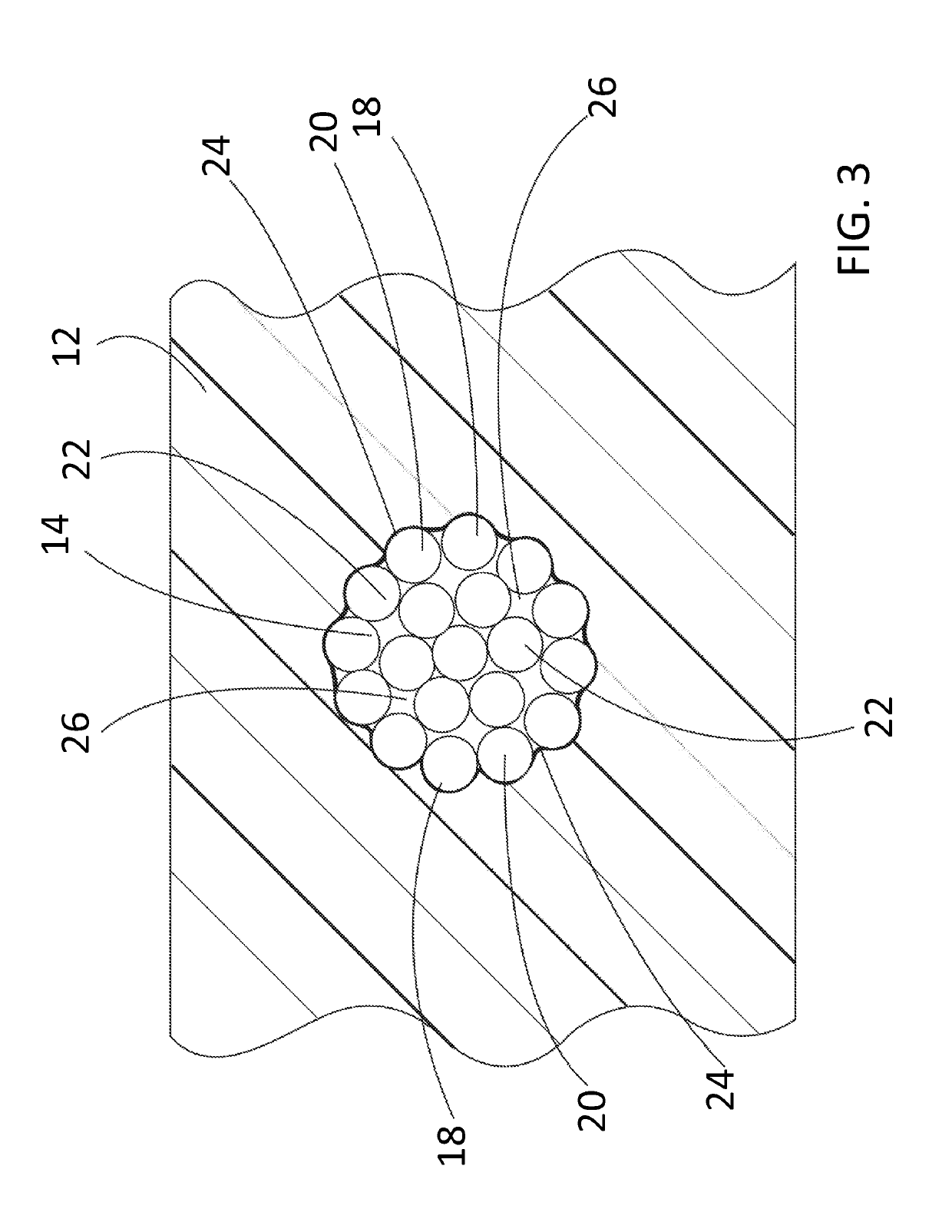
[0011]Each vibration-damping rope includes an outer layer of wires that surrounds a plurality of inner wires. The rope is tightly bound such that the inflowing composite material is prevented from passing by the outer layer of wires to which it adheres and into the inner wires during the manufacturing process. Accordingly, the voids between the inner wires are free of composite material, thereby allowing sliding movement of the inner wires relative to one another and to the outer wires to dampen resonant vibration of the component.

Problems solved by technology

Dynamic loading can cause composites to fail on both the microscopic or macroscopic scale.
Macroscopic scale failures can be net section failures of the part due to material fatigue resulting from the cyclic variation of the induced stress.
A microscopic scale failure can occur when one or more of the layers in the composite fail in tension of the matrix or in the bond between the matrix and fibers or at each individual reinforcing fiber in compression buckling.
This can occur due to either material fatigue resulting from the cyclic variation of the induced stress or due to high instantaneous stress caused by the impact or shock loading.
The poor performance of the known composite materials under dynamic loading is mainly attributed to their relatively low internal damping, i.e., their inability to quickly convert vibrational or impact energy to heat or sound.
The expanded use of composite materials is further restricted according to known technology as composites are generally known to have relatively poor bearing strength when compared to metals.

Method used


Image

  • Composite materials having embedded metal ropes for increased damping capacity and methods of manufacturing same
  • Composite materials having embedded metal ropes for increased damping capacity and methods of manufacturing same
  • Composite materials having embedded metal ropes for increased damping capacity and methods of manufacturing same

Examples


Embodiment Construction

[0025]In the following figures, the same reference numerals will be used to refer to the same components. In the following description, various operating parameters and components are described for different constructed embodiments. These specific parameters and components are included as examples and are not meant to be limiting.

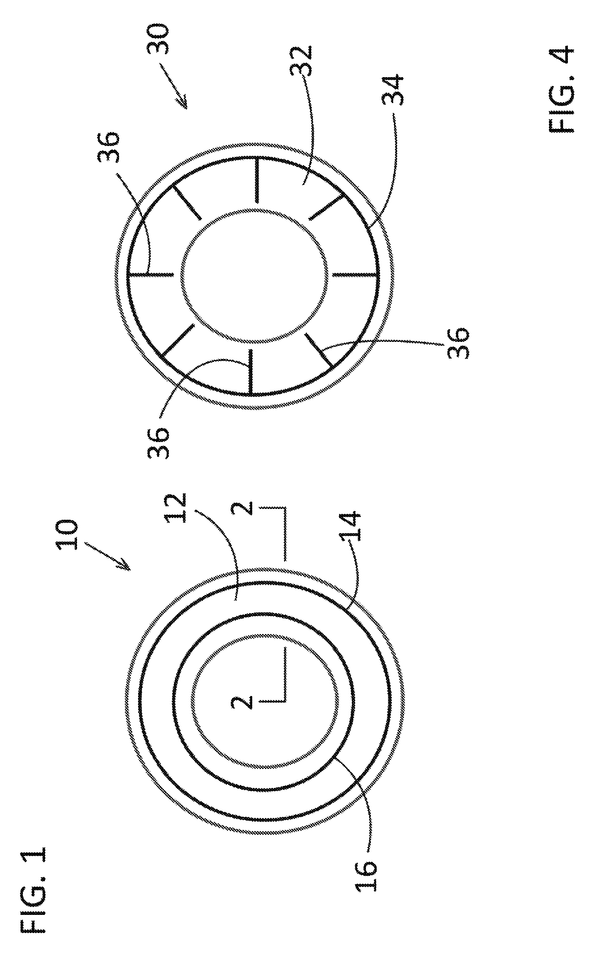
[0026]The accompanying figures and the associated description illustrate the construction and use of vibration-damping ropes in composite material according to the disclosed inventive concept. Particularly, FIGS. 1 through 6 illustrate the rope embedded in several individual components for use in multiple applications. FIGS. 7 through 9 illustrate the rope embedded in a beam shown in multiple applications. It is to be understood that the illustrated configurations are suggestive only and are not intended as being limiting as other configurations may be adapted for use with the rope embedded in a composite material without deviating from either the spirit or...


PUM

PropertyMeasurementUnit
friction coefficientaaaaaaaaaa
tensile strengthaaaaaaaaaa
damping capacityaaaaaaaaaa

Abstract

A method and system for increasing damping capacity utilizing dry friction between individual wires of a rope embedded in a component formed from a composite is illustrated. The individual wires allow inter-wire friction to occur during part vibration. The component includes a body that is a molded matrix formed form a composite material. The body may be of any material selected from the group consisting of a polymer, a metal or a ceramic material. One or more vibration-damping ropes are embedded in the body. The vibration-damping ropes may be elongated segments or may be a rope having connected ends that form one or more rings. Each vibration-damping rope includes an outer layer of wires that surrounds a plurality of inner wires. Inflowing composite material is prevented from passing by the outer layer of wires and into the inner wires during the manufacturing process, thereby forming voids between the inner wires.

Description

TECHNICAL FIELD[0001]The disclosed inventive concept relates to components, such as vehicle components, made from composite materials. More particularly, the disclosed inventive concept relates to such components having metal cables or ropes embedded into the composite material during the molding process. The damping capacity is increased by providing such cables or ropes comprising plural individual wires that are either linear or twisted relative to one another and are embedded into the part during the molding process.BACKGROUND OF THE INVENTION[0002]Composite materials are used in a wide variety of applications, particularly in the automotive sector. Such applications include, for example, vehicle body panels as well as vehicle frame components. Newer wheel constructions include composite materials being used as center elements attached to aluminum rims.[0003]The composite material used in such applications is made by combining two or more individual materials in both continuous ...

Claims


Application Information

Patent Timeline
Patent Type & Authority Patents(United States)
IPC IPC(8): F16F7/02F16F15/02B29C45/14B29C70/70B29K101/12B29K705/12B29L31/00B29L31/30
CPCB29C45/14549F16F15/02B29C45/14631B29C70/70F16F7/02B29L2031/30F16F2222/04B29K2101/12B29K2705/12B29L2031/721F16F1/366F16F2224/0241
Inventor KARPENKO, YURI ANATOLY
Owner FORD GLOBAL TECH LLC
Why Eureka
Eureka Blog
Learn More