
Vehicle oil pump driving control device

a technology for oil pumps and control devices, which is applied in the direction of gearing control, gear lubrication/cooling, gearing elements, etc., can solve the problems of deteriorating fuel efficiency or electricity efficiency, increasing consumption energy used as pump driving energy, etc., and reducing the driving energy of the pump to drive the oil pump. , the effect of reducing the consumption energy

Active Publication Date: 2019-12-10
JATCO LTD
View PDF20 Cites 3 Cited by
  • Summary
  • Abstract
  • Description
  • Claims
  • Application Information

AI Technical Summary

Benefits of technology

[0005]The present invention was made in view of the above technical problem. An object of the present invention is therefore to provide a vehicle oil pump driving control device that is capable of achieving reduction of the consumption energy during the vehicle stop.
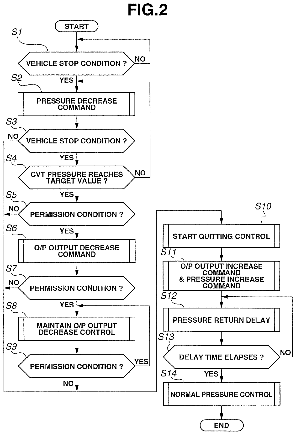
[0006]To achieve the above object, an oil pump driving control device of a vehicle having an oil pump that is driven by a vehicle-mounted power source and produces a pump discharge oil to a hydraulic pressure working unit provided on a driving force transmission line, comprises: a controller configured to control a pump drive of the oil pump. And, the controller is configured to perform a control so that during vehicle stop, the lower a working fluid temperature is, the more a pump driving energy to drive the oil pump is decreased.
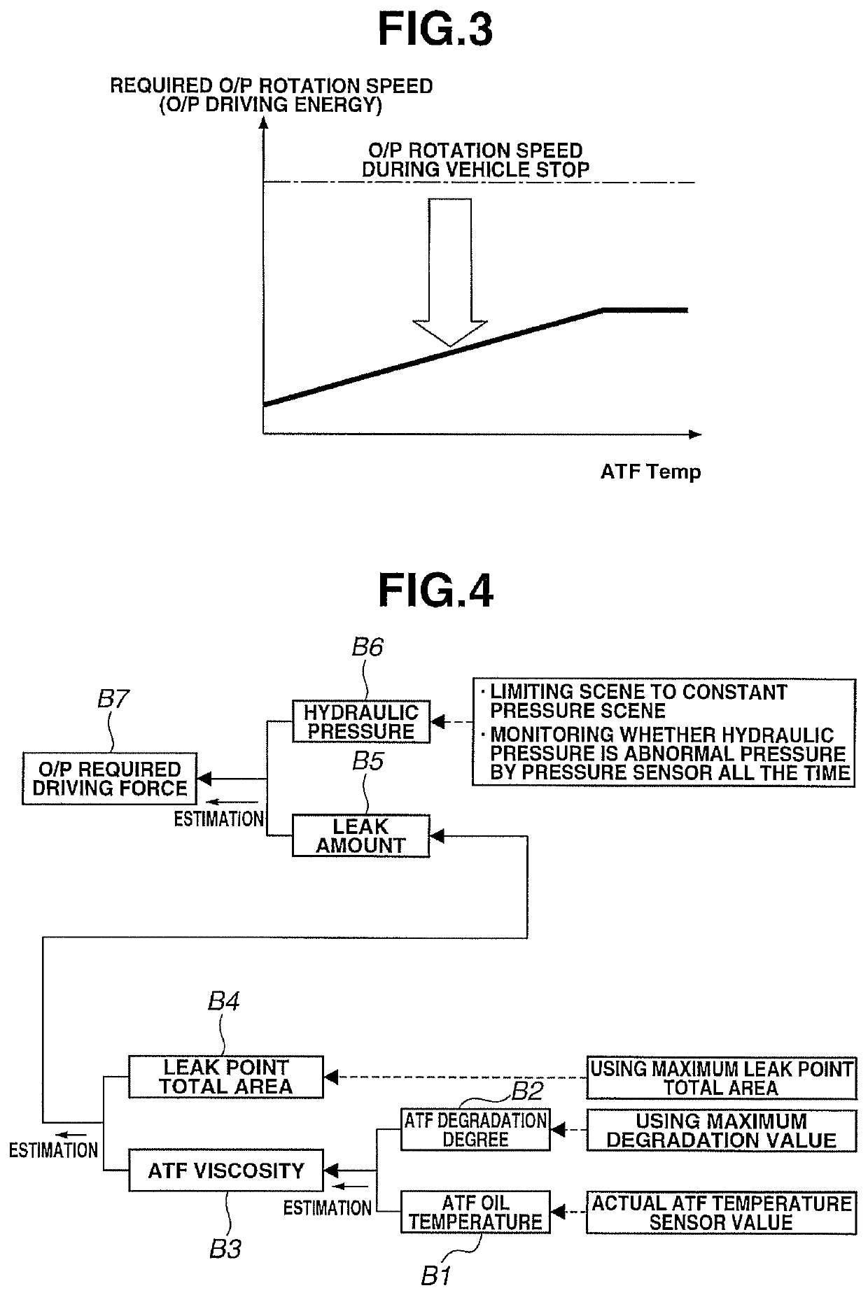
[0007]Therefore, the control so that during vehicle stop, the lower the working fluid temperature is, the more the pump driving energy to drive the oil pump is decreased is performed. That is, when the working fluid temperature is low, a viscosity of the working fluid becomes high, and thus the leak amount from the hydraulic circuit of hydraulic pressure working unit becomes small, thereby reducing an oil pump discharge amount required when outputting a constant pressure. When focusing attention on this point and performing the control so that during the vehicle stop during which a change of the oil pressure does not occur, the lower the working fluid temperature is, the more the pump driving energy to drive the oil pump is decreased, the leak amount from the hydraulic circuit of the hydraulic pressure working unit is compensated with the oil pump discharge amount. In this manner, by performing the oil pump driving control during the vehicle stop with the leak amount from the hydraulic circuit being focused on, the consumption energy used as the pump driving energy is reduced. As a consequence, it is possible to achieve the reduction of the consumption energy during the vehicle stop.

Problems solved by technology

Therefore, as a problem, consumption energy used as pump driving energy is increased, and consequently, fuel efficiency or electricity efficiency is deteriorated.

Method used


Image

  • Vehicle oil pump driving control device
  • Vehicle oil pump driving control device
  • Vehicle oil pump driving control device

Examples


embodiment 1

[0018]First, a configuration will be explained.

[0019]An oil pump driving control device of an embodiment 1 is a control device applied to an FF hybrid vehicle (as an example of vehicles) in which a belt-type continuously variable transmission is mounted as a transmission with right and left front wheels being driving wheels. In the following description, a configuration of the oil pump driving control device for the FF hybrid vehicle of the embodiment 1 will be separately explained by [General system configuration] and [Oil pump driving control process configuration].

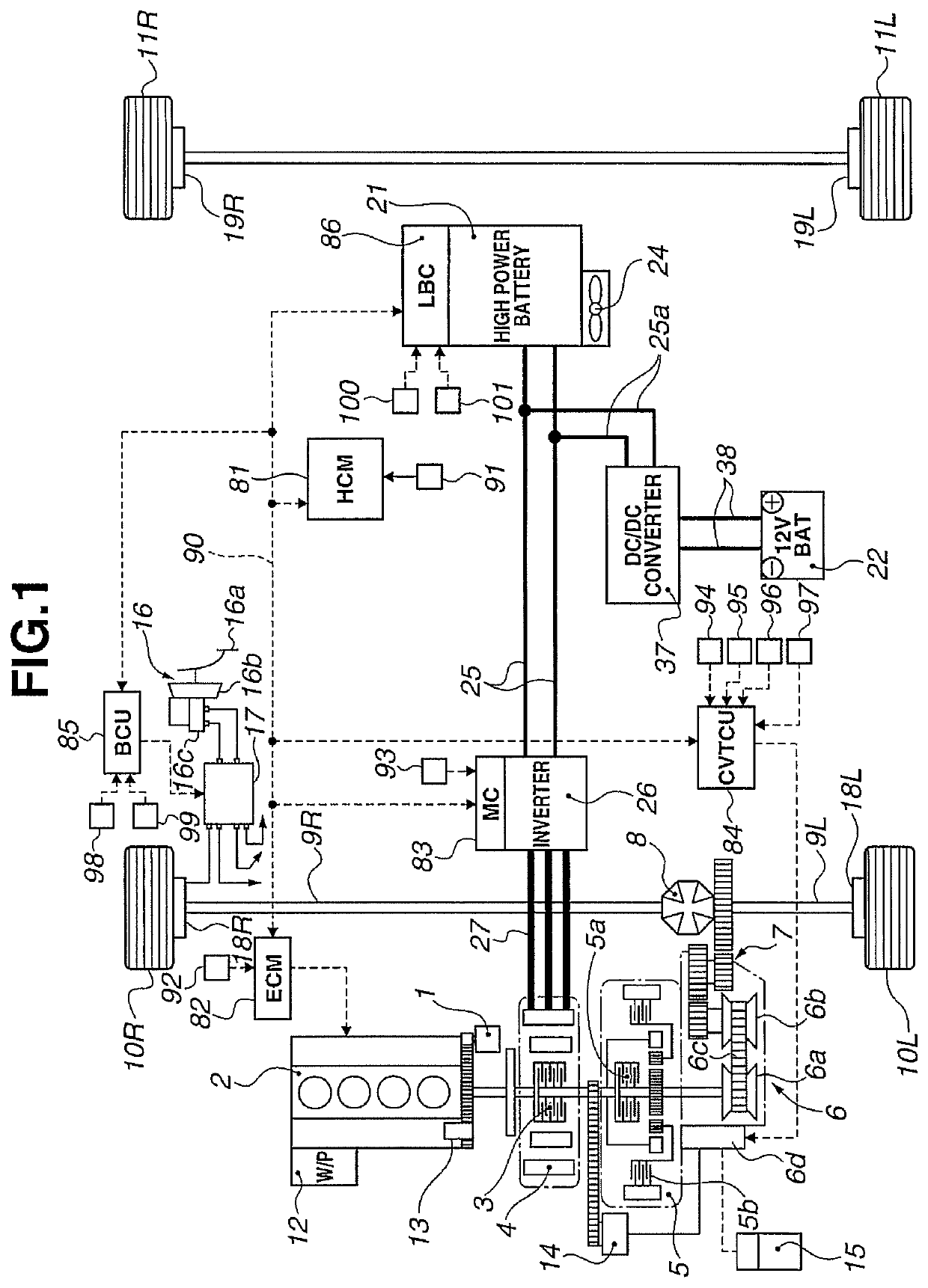
[0020][General System Configuration]FIG. 1 shows a general system of the FF hybrid vehicle to which the control device of the embodiment 1 is applied. A general system diagram of the FF hybrid vehicle will be explained below with reference to FIG. 1.

[0021]As shown in FIG. 1, a driveline of the FF hybrid vehicle has a transverse engine (a transversely mounted engine) 2, a first clutch 3 (called “CL1” for short), a motor / ...


PUM


Abstract

An oil pump driving control device of a vehicle having a main oil pump (14) that is driven by a motor / generator (4) and produces a pump discharge oil to a first clutch (3), a second clutch (5) and a belt-type continuously variable transmission (6) provided on a driving force transmission line. A hybrid control module (81) is provided in this FF hybrid vehicle. The hybrid control module (81) is configured to perform a control so that during vehicle stop, the lower an ATF oil temperature is, the more the pump driving energy to drive the main oil pump (14) is decreased. With this control, consumption energy during the vehicle stop can be reduced.

Description

[0001]The present invention relates to a vehicle oil pump driving control device that controls drive of an oil pump generating a pump discharge oil to a hydraulic pressure working unit (such as a transmission and a clutch) provided on a driving force transmission line during vehicle stop.BACKGROUND ART[0002]There has been known, for instance, by Patent Document 1, a related art driving control device of a transmission oil pump that when an ATF oil temperature (=a transmission working fluid temperature) is low, in order to immediately increase the ATF oil temperature after a low temperature start, feeds the transmission working fluid to an ATF warmer by driving an electric motor-driven oil pump.[0003]In the related art driving control device, however, the electric motor-driven oil pump is driven when the ATF oil temperature is the low oil temperature at which a viscosity of the transmission working fluid is high. Because of this, when feeding the transmission working fluid to the ATF...

Claims


Application Information

Patent Timeline
Patent Type & Authority Patents(United States)
IPC IPC(8): F16H61/00F16H59/72F16H57/04
CPCF16H61/0025F16H59/72F16H57/0434F16H61/0028
Inventor MOURI, TAKANOBUONOYAMA, TAIICHISHIMAMURA, SEISHIKANEKO, KAKUZOUTOYOFUKU, AKIHIROARAI, RYUICHINOGUCHI, RYUZOHARUI, SATOSHIMIYAISHI, HIRONORIMIZUOCHI, TOMOYUKIWATANABE, KENICHIFUJIKAWA, MASUMIKOTSUJI, KOUICHISUZUKI, SHINGOSUZUKI, AKITOIZUMI, TETSUYAIWADO, KEISUKEMIYACHI, KAZUHIRO
Owner JATCO LTD
Learn More