
Transmission method with double directivity

a transmission method and directivity technology, applied in transmission, modulated carrier systems, channel dividing arrangements, etc., can solve the problems of difficult propagation conditions, high free space loss, and important challenges to overcome, and achieve spatial multiplexing gains and high efficiency

Active Publication Date: 2019-12-17
CARVALHO PAULO MIGUEL +4
View PDF6 Cites 2 Cited by
  • Summary
  • Abstract
  • Description
  • Claims
  • Application Information

AI Technical Summary

Benefits of technology

The patent describes a method for transmitting signals with multiple antennas using a technique called massive MIMO. The method allows for the use of large constellations and highly-efficient amplifiers, which can reduce interference between users and ensure secure communications at the physical layer. The method also uses spatial multiplexing gains, which improve the transmission of signals in the desired direction. Overall, the patent presents a technique for improving the efficiency and reliability of MIMO communications.

Problems solved by technology

However, there are important challenges that need to be overcome when implementing those systems, both at the hardware level and due to the hostile propagation conditions.
However, there are important challenges associated to the implementation of mm-wave systems, namely the high free space losses and difficult propagation conditions (e.g., small diffraction effects, huge losses due to obstacles) and difficulties at the hardware level.
This combined with the large bit rates, means that the power requirements are much more severe than with conventional, sub-6 GHz, communications.
This is particularly important for systems that also require high spectral efficiencies (i.e., large constellations), which not only have higher power requirements but are also associated to signals with higher envelope fluctuations and higher PAPR (Peak-to-Average Power Ratio), which leads to lower amplification efficiency [4].
Another problem associated to broadband mm-wave communications is the frequency selectivity of the channel, since the good reflection properties of most materials at these frequencies lead to rich multipath environments.
However, since these amplifiers are strongly nonlinear, they should only be employed for signals with constant or quasi-constant envelope.

Method used


Image

  • Transmission method with double directivity
  • Transmission method with double directivity
  • Transmission method with double directivity

Examples


Embodiment Construction

[0042]The present application describes a transmission method using a multi-antenna transmitter combined with a frequency-domain receiver for broadband mm-wave systems based on large and dense constellations. This transmitter is compatible with efficient, low-cost, nonlinear amplifiers, while allowing spatial multiplexing gains. Referring to the figures, it will now be described technology using different embodiments of the same technology, which is not intended to limit the scope of protection of this application. The embodiments are composed by a method of sequential steps as described below.

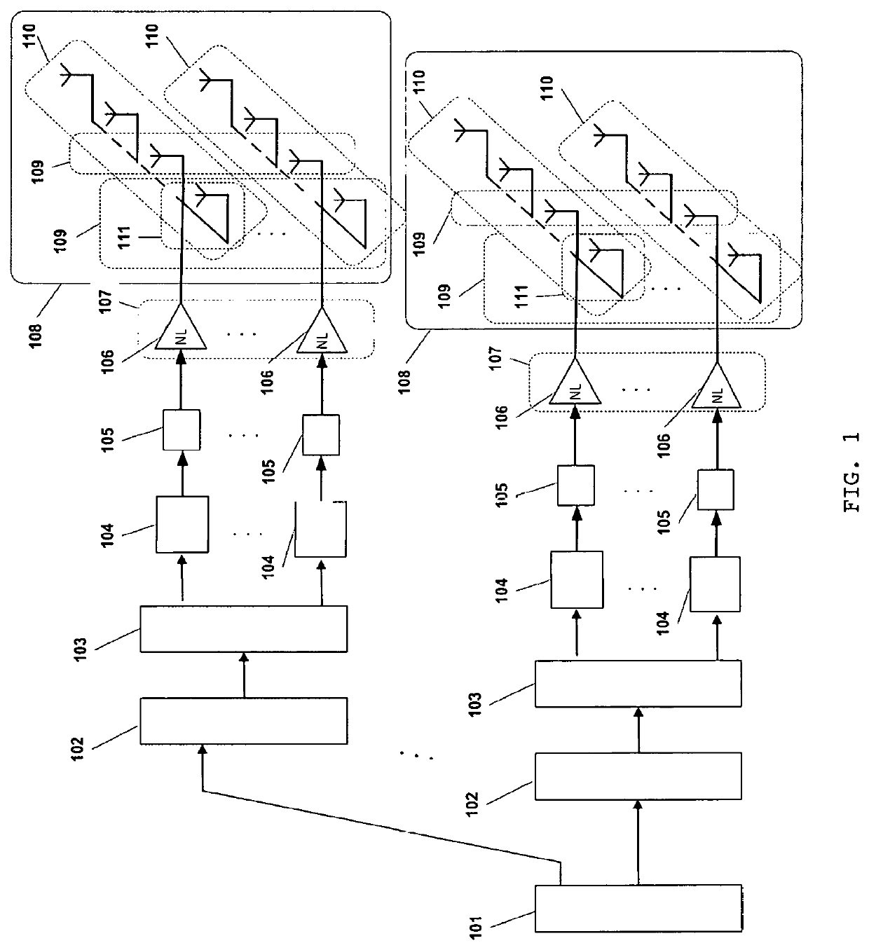
[0043]The transmission method uses SC-FDE schemes, combined with offset modulations with large constellations, for high spectral efficiency mm-wave communications. To allow highly efficient, strongly nonlinear power amplifiers, the variable envelope signals associated to large constellations are decomposed as the sum of several polar components [8], each one modulated as a serial OQPSK signal ...


PUM


Abstract

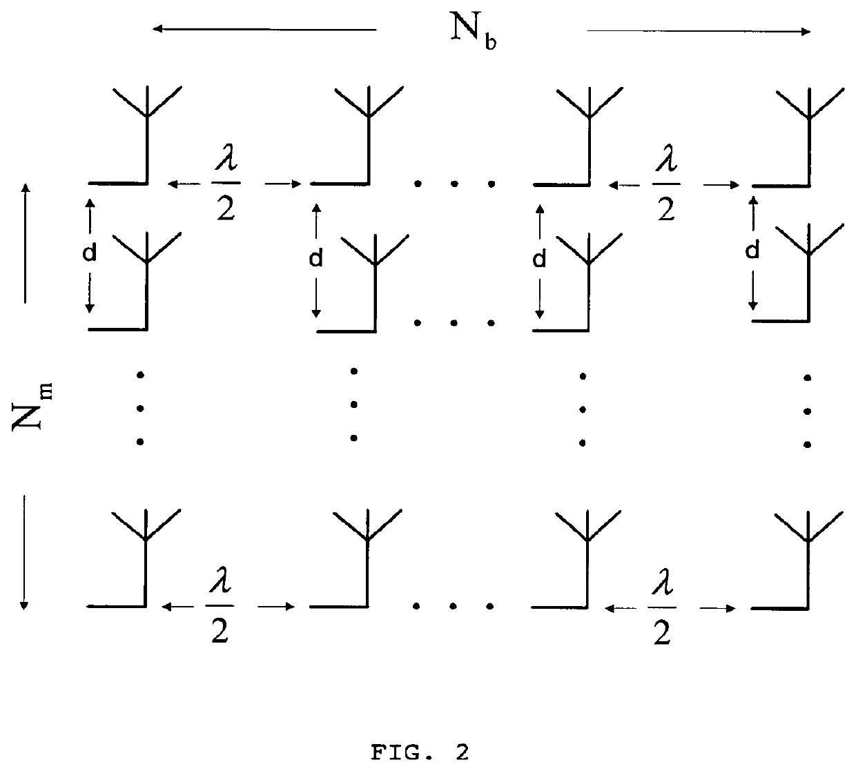
A transmission method using a massive MIMO (Multiple-Input and Multiple-Output) scheme with an arrangement 108 of Nm×Nb antenna elements at the transmitter, arranged in Nm sets of Nb antenna elements or Nb sets of Nm antenna elements based on SC-FDE (Single-Carrier with Frequency Domain Equalization) schemes with large constellations that is compatible with low-cost, highly-efficient, nonlinear amplifiers 106, while allowing spatial multiplexing gains.The transmission structure of this transmission method decomposes in 103 the modulated symbols from 102 associated to a given constellation as the sum of Nm polar components that are modulated as Nm BPSK (Binary Phase Shift Keying) signals. Each of these BPSK signals can be regarded as an OQPSK (Offset Quadrature Phase Shift Keying) signal in the serial format that is specially designed to have good tradeoffs between reduced envelope fluctuations and a compact spectrum.

Description

BACKGROUND OF THE INVENTION[0001]Field of the Invention[0002]The present invention relates to telecommunication systems. More particularly, the present invention relates to transmission methods which make use of architectures of the type massive MIMO (Multiple-Input Multiple-Output) based on SC-FDE (Single-Carrier with Frequency Domain Equalization) schemes with large constellations that is compatible with low-cost, highly-efficient, nonlinear amplifiers, while allowing spatial multiplexing gains.[0003]Description of Related Art[0004]It is well-known that mm-wave (millimeter wave) communications have high potential for future wireless broadband systems. However, there are important challenges that need to be overcome when implementing those systems, both at the hardware level and due to the hostile propagation conditions. This is specially important for spectrally efficient communications based on large constellations, since the power requirements are higher, as well as the amplific...

Claims


Application Information

Patent Timeline
Patent Type & Authority Patents(United States)
IPC IPC(8): H04B7/0426H04L25/14H04B7/0456H04L27/18H04L27/26
CPCH04B7/0469H04B7/043H04L25/14H04B7/0434H04L27/2636H04L27/18
Inventor CARVALHO, PAULO MIGUELGOMES, MARCO ALEXANDREDINIS, RUI MIGUELSILVA, VITOR MANUELBENTO, PEDRO DANIEL
Owner CARVALHO PAULO MIGUEL
Learn More