Power transmission control method and device for crane and crane

a technology of power transmission control and crane, which is applied in the direction of mechanical equipment, transportation and packaging, and lifting equipment, etc., can solve the problems of not being applicable to such super-tonnage engineering, wasting a large amount of kinetic energy, and the weight of the crane, so as to improve the service life and energy recovery efficiency of the secondary element, improve the comfort and safety of the driver, and reduce the effect of power impact generated by the hybrid power system during gear shi

Active Publication Date: 2020-01-28
XUZHOU HEAVY MASCH CO LTD
View PDF22 Cites 0 Cited by
  • Summary
  • Abstract
  • Description
  • Claims
  • Application Information

AI Technical Summary

Benefits of technology

[0010]To this end, a technical problem to be solved by the present invention is provide a power transmission control method for a crane, which can control the maximum displacement of the secondary element for different gears.
[0016]According to an embodiment of the present invention, the method further includes: multiplying the working displacement of the secondary element by a preset second buffer coefficient to obtain an actual working displacement of the secondary element when a forward rotating speed of the transmission shaft is determined within a preset buffer rotating speed range, and reducing the actual working displacement of the secondary element to zero when the forward rotating speed of the transmission shaft is the minimum effective rotating speed.
[0025]According to the power transmission control method and device for the crane and the crane of the present invention, the maximum displacement of the secondary element is controlled for different gears, thus the power impact generated by the hybrid power system during gear shift can be effectively reduced. A buffer mode is added during energy release, utilization and recovery to avoid influence on a vehicle due to loss of instant power generated at the moment of energy release completion and avoid vehicle jitter due to instable power resulting from the vehicle at low speed or the system suddenly disconnected, thus improving the comfort and safety of the driver, and the rotating speed of the secondary element is limited, which can improve the service life and energy recovery efficiency of the secondary element.

Problems solved by technology

In addition, the crane is heavy, and has a higher speed relative to other engineering machinery vehicles, so use of the traditional mechanical friction braking manner will cause waste of a large amount of kinetic energy.
In the current automobile industry, mostly used is the oil-electric hybrid power technology, which is generally applied to limousines and buses but is not applicable to such super-tonnage engineering vehicle as the wheeled crane due to cost and driving force problems.
However, during the research of applying oil-hydraulic hybrid power to the wheeled crane, it is found that the hydraulic system often has a large operating torque and its performance is not easy to control.
When the hydraulic system is applied to a multi-gear vehicle, it is very likely to cause large influence on the vehicle if output control of the braking force and the driving force is unreasonable, and particularly when the difference of gear speed ratios is large, the difference of required torques is large too.
Currently, domestic research on oil-hydraulic hybrid power is not deep enough, and particularly oil-hydraulic hybrid power has not been applied to such an engineering machinery product as the wheeled crane.
Such a control method ignores the influence of gears, without considering the problem that different gears generate power impact on a vehicle, and such a problem is particularly obvious for a hybrid power system with a front engine, which will reduce the service life of the hybrid power system and cause certain influence on driving comfort of a driver at the same time and driving safety is also affected.
In the prior control method steps, since hybrid power control is not actually made to such a vehicle as the wheeled crane, some characteristics of the crane itself are not considered, for example, the crane has large inertia, relatively high speed and many gears, and in the prior method, the problems of power impact generated in processes of energy storage and release and driving comfort of the driver are not considered.
For a hybrid power system with a front engine, the same torque provided by a secondary element will be increased by several or a dozen of times after being transferred to a transmission shaft, thus will generate a bigger power impact; Second, in the prior method steps, it is also not considered that at the moment of energy release completion, the problem of instantaneous driving force reduction due to sudden disappearance of the driving torque provided by the secondary element will cause power impact, which not only does not conform to the operation habit of the driver but also influences the driving comfort of the driver, and seriously, it will even influence judgment of the driver and affect safety;
Third, in the prior art method, the influence of the rotating speed on a recovery process is not considered.

Method used


Image

  • Power transmission control method and device for crane and crane
  • Power transmission control method and device for crane and crane
  • Power transmission control method and device for crane and crane

Examples


Embodiment Construction

[0031]The present invention will be described more comprehensively with reference to the accompanying drawings in which exemplary embodiments of the present invention are illustrated. Technical solutions in the embodiments of the present invention will be described below clearly and completely in combination with the accompanying drawings in the embodiments of the present invention. Obviously, the described embodiments are merely a part of, instead of all of, the embodiments of the present invention. Based on the embodiments in the present invention, all other embodiments obtained by those of ordinary skill in the art without creative effort are within the protection scope of the present invention. The technical solution of the present invention will be described below in multiple aspects in conjunction with various figures and embodiments.

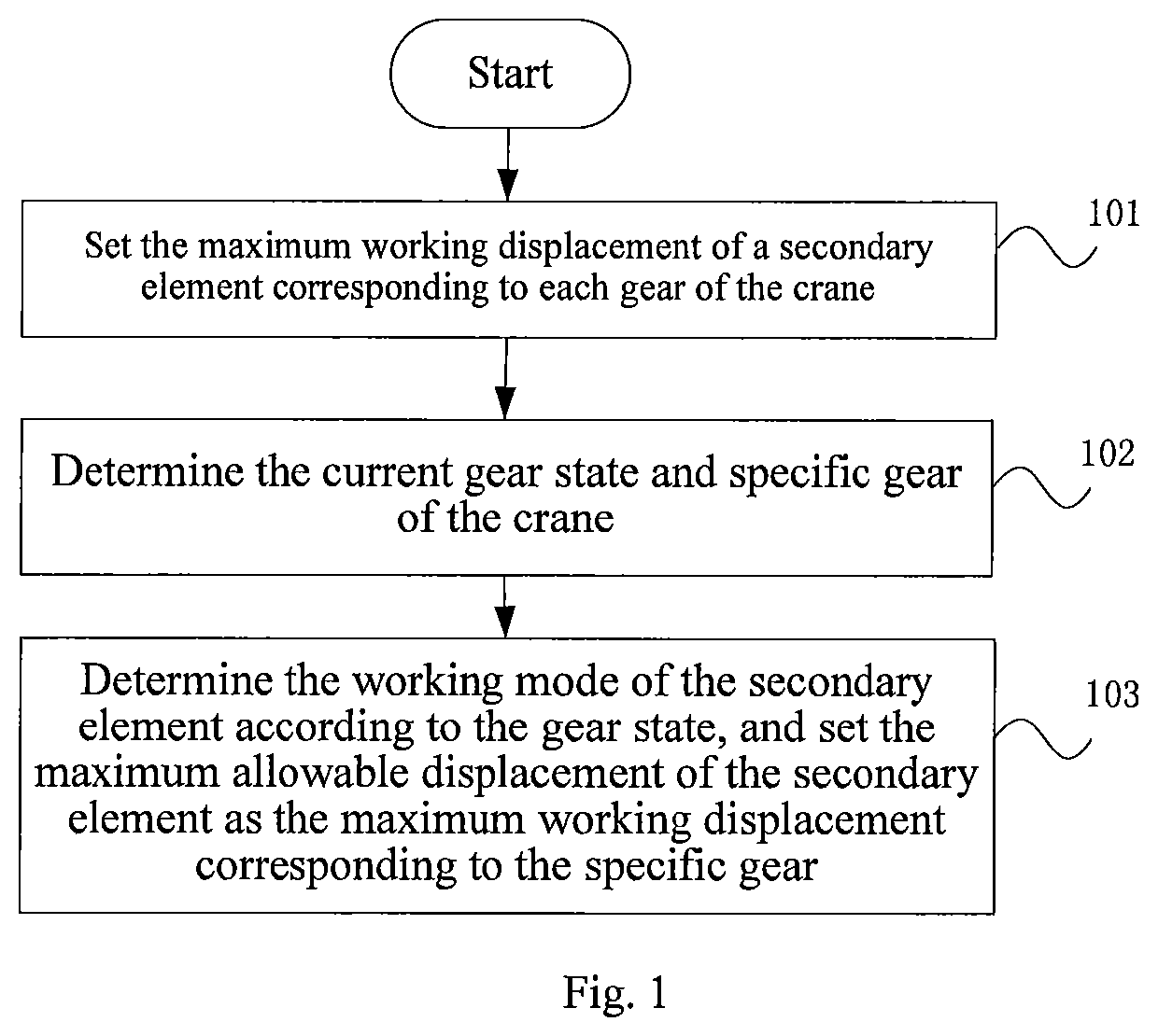
[0032]FIG. 1 is a flow chart of an embodiment of a power transmission control method for a crane according to the present invention, the power tr...


PUM


Abstract

The present invention discloses a power transmission control method and device for a crane and the crane. The method includes: setting the maximum working displacement of a secondary element corresponding to each gear of the crane; determining the current gear state and specific gear of the crane; determining the working mode of the secondary element from the gear state, and setting the maximum allowable displacement of the secondary element as the maximum working displacement corresponding to the specific gear.

Description

RELATED APPLICATIONS[0001]The present application is a 35 U.S.C. § 371 national phase application of PCT International Application No. PCT / CN2015 / 093973, filed Nov. 6, 2015, which claims priority to Chinese Patent Application No. 201410720540.7 filed Dec. 2, 2014, the disclosures of which are hereby incorporated herein by reference in their entireties.FIELD OF THE INVENTION[0002]The present invention relates to the technical filed of engineering machinery, and in particular to a power transmission control method and device for a crane and the crane.BACKGROUND OF THE INVENTION[0003]With rapid development of industrial technologies around the world, problems of energy shortage and environmental pollution are increasingly serious, and the hybrid power technology is regarded as one of the effective solutions for solving the problems of energy shortage and environmental pollution. A wheeled crane mostly travels in urban areas or among cities, but due to influence of road environment, fre...

Claims


Application Information

Patent Timeline
Patent Type & Authority Patents(United States)
IPC IPC(8): B66C13/18B66C23/00F16H61/02F16H59/36B60K6/12F15B1/02B66C13/00B60W50/00
CPCB60K6/12F16H59/36B66C23/54B66C13/18F15B1/022B66C13/00F16H61/02F15B1/02B60W2300/16Y02T10/92B60W2050/0026B60W2510/101B60W2510/1005Y02T10/6208Y02T10/62
Inventor SHAN, ZENGHAIDONG, QUANWANG, SHUAIXIAO, YUNBOZHANG, ZHENDEKONG, JIEZHAO, JING
Owner XUZHOU HEAVY MASCH CO LTD
Why Eureka
Try Eureka