Systems and methods for battery charge control

a technology of system and method, applied in the direction of battery/fuel cell control arrangement, battery overheat protection, safety/protection circuit, etc., can solve the problems of battery pack being battery pack energy available decreases, and the battery pack is typically not yet fully charged, so as to limit the possibility of overcharging and damage to the battery, increase the energy stored in the battery at full charge, and reduce the effect of overcharging

Active Publication Date: 2020-01-28
TOYOTA JIDOSHA KK
View PDF6 Cites 0 Cited by
  • Summary
  • Abstract
  • Description
  • Claims
  • Application Information

AI Technical Summary

Benefits of technology

[0005]The inventors of the present invention desire to enable increasing energy stored in a battery at full charge while limiting the possibility for overcharging of and damage to the battery.
[0007]By providing such a system it may be possible to discount an allowable voltage range to more completely charge a battery that has undergone degradation. This in turn enables greater energy availability with reduced risk of damage to the battery.
[0021]By providing such a method it may be possible to discount an allowable voltage range to more completely charge a, battery that has undergone degradation. This in turn enables greater energy availability with reduced risk of damage to the battery.

Problems solved by technology

During charging of a battery, e.g., a lithium ion battery, total voltage at the battery pack may increase sharply due to increasing overvoltage at certain laminating parts at which degradation has occurred.
However, as degradation of the battery progresses the battery pack is typically not yet fully charged (i.e., state of charge (SOC)<100%) when charging is stopped as a result of reaching the upper bound voltage.
Therefore, available amount of energy from the battery decreases due to the degradation dispersion.
However, US 2004 / 0096749 does not take into consideration the influence of overvoltage when the battery has degraded due to use.

Method used


Image

  • Systems and methods for battery charge control
  • Systems and methods for battery charge control
  • Systems and methods for battery charge control

Examples


Embodiment Construction

[0038]Reference will now be made in detail to the present exemplary embodiments of the disclosure, examples of which are illustrated in the accompanying drawings. Wherever possible, the same reference numbers will be used throughout the drawings to refer to the same or like parts.

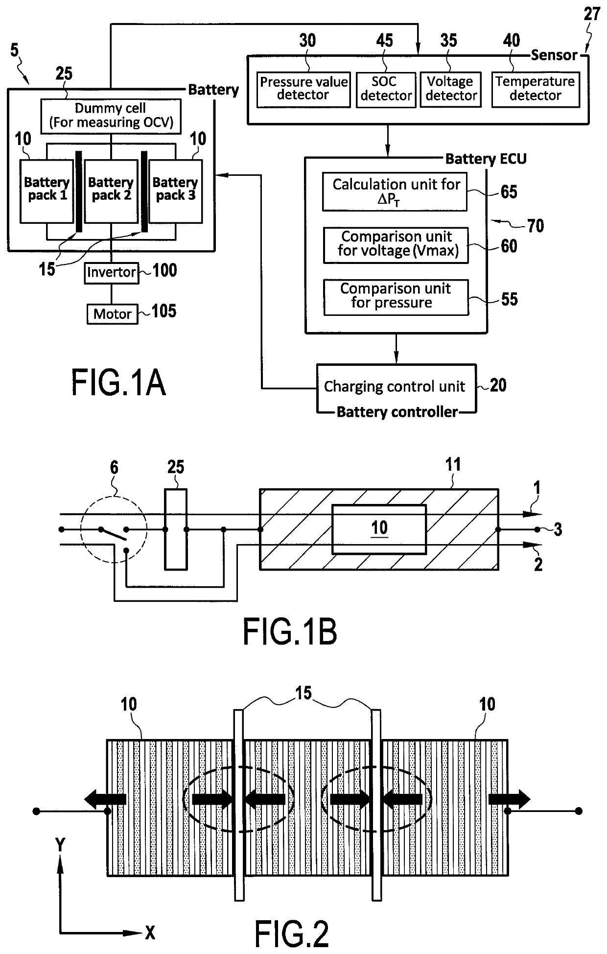
[0039]FIG. 1A is a schematic diagram of a charging system for a battery according to embodiments of the present disclosure. The system may include a battery 5, one or more sensors 27, battery control unit 70, and a charging control unit 20. Battery 5 may include one or more battery packs 10, one or more pressure sensing membranes 15, and a dummy cell 25, among others. Battery 5 may be any suitable type of battery, for example, a lithium ion battery, a NIMH battery, lead acid battery, etc.

[0040]Battery 5 may be connected to an inverter 100 which may in turn be connected to one or more motors 105, to permit energy stored in battery 5 during a charging process to be stepped up by inverter 100 and fed to motor ...


PUM


Abstract

A charging control system for a battery includes a temperature sensor, a voltage sensor, a pressure sensor, and a controller. The controller is configured to determine a threshold pressure change associated with a full charge of the battery based on map data selected from a predetermined data map associated with the battery, monitor a present voltage value obtained by the voltage sensing means and a total pressure change based on a present pressure value obtained by the pressure sensing means, continue the charging process when the present voltage value exceeds an upper limit voltage value, and total pressure change is less than threshold pressure change, and terminate the charging process when the present voltage value exceeds the upper limit voltage value, and the total pressure change is greater than or equal to the threshold pressure change.

Description

FIELD OF THE DISCLOSURE[0001]The present disclosure is related to systems and methods for controlling charging of a battery. More particularly, the present disclosure is related to managing a charge state based on an internal pressure measure within the battery.BACKGROUND OF THE DISCLOSURE[0002]During charging of a battery, e.g., a lithium ion battery, total voltage at the battery pack may increase sharply due to increasing overvoltage at certain laminating parts at which degradation has occurred. Thereby, total voltage reaches an upper bound voltage, which is set in order to prevent overcharging, and the charging system stops charging considering that the battery pack is fully charged.[0003]However, as degradation of the battery progresses the battery pack is typically not yet fully charged (i.e., state of charge (SOC)<100%) when charging is stopped as a result of reaching the upper bound voltage. Therefore, available amount of energy from the battery decreases due to the degrad...

Claims


Application Information

Patent Timeline
Patent Type & Authority Patents(United States)
IPC IPC(8): H02J7/04H02J7/14H02J7/00B60L58/24B60L58/15
CPCB60L58/24H02J7/0029B60L58/15H02J7/14H02J7/00719H02J7/00302B60L58/10Y02T10/70Y02T10/7072Y02T90/14H02J7/00309H02J7/007192
Inventor KOMIYAMA, KEITAKATOH, YUKI
Owner TOYOTA JIDOSHA KK
Why Eureka
Try Eureka