Power amplifier module, frontend circuit, and communication device

a technology of power amplifier and frontend circuit, which is applied in the direction of low noise amplifier, rf amplifier, transmission, etc., can solve the problems of increasing power noise, and achieve the effect of reducing power noise and power nois

Active Publication Date: 2020-02-04
MURATA MFG CO LTD
View PDF18 Cites 6 Cited by
  • Summary
  • Abstract
  • Description
  • Claims
  • Application Information

AI Technical Summary

Benefits of technology

[0007]The present disclosure has been made in order to address the issue described above, and an object thereof is to provide a power amplifier module and a communication device in which power noise is reduced.
[0029]According to the present disclosure, it is possible to provide a power amplifier module and a communication device in which power noise is reduced.

Problems solved by technology

In the power amplifier module that is formed on the multilayer substrate as described above, an inductance component is generated in a grounded part of a power amplifier element due to a wiring line that connects an amplifier and a ground layer formed in the multilayer substrate to each other and causes an increase in power noise, which is an issue.

Method used


Image

  • Power amplifier module, frontend circuit, and communication device
  • Power amplifier module, frontend circuit, and communication device
  • Power amplifier module, frontend circuit, and communication device

Examples


first embodiment

[0040][1.1 Circuit Configuration of PA Module 1 According to First Embodiment]

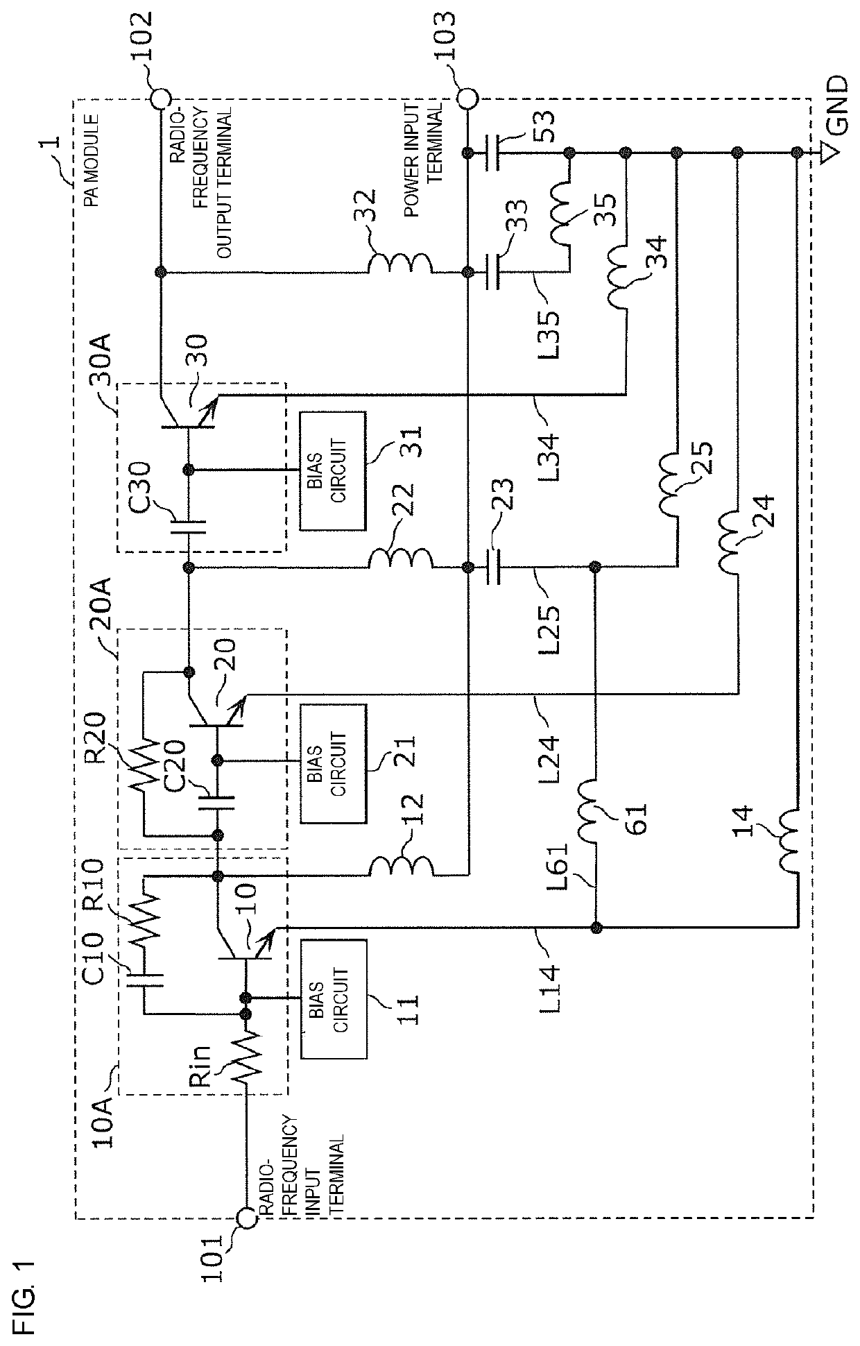
[0041]FIG. 1 is an equivalent circuit diagram of a PA (power amplifier) module 1 according to a first embodiment. The PA module 1 (power amplifier module) illustrated in FIG. 1 includes a radio-frequency input terminal 101, a radio-frequency output terminal 102, a first amplifier circuit 10A, a second amplifier circuit 20A, a third amplifier circuit 30A, bias circuits 11, 21, and 31, choke coils 12, 22, and 32, bypass capacitors 23, 33, and 53, a first wiring line L14, a second wiring line L24, a third wiring line L25, a fourth wiring line L61, a sixth wiring line L34, and a seventh wiring line L35.

[0042]The PA module 1 is configured such that the above-described constituent elements are mounted on or in a multilayer substrate. This multilayer substrate has a ground pattern layer (corresponding to GND in FIG. 1) that is connected to the ground terminal of a power source.

[0043]The first amplifier circuit 10...

second embodiment

[0091]The PA module 1 or 2 according to the first embodiment or the modification thereof is applicable to a PA module of an envelope tracking system. In a second embodiment, a PA module of an envelope tracking system will be described.

[0092]FIG. 7 is a circuit configuration diagram of a PA module 3 according to the second embodiment. The PA module 3 illustrated in FIG. 7 includes the PA module 1 and a supply modulator 75 and operates in accordance with an envelope tracking system (hereinafter referred to as “ET system”).

[0093]The PA module 1 is the PA module according to the first embodiment and is configured so as to be capable of reducing power noise.

[0094]The supply modulator 75 modulates a DC voltage supplied from the power source 70 in accordance with amplitude information (envelope) about output power inputted from an AM signal input terminal 104 and applies the modulated voltage to the collector terminal of each of the amplifier transistors 10, 20, and 30 via the power input ...

third embodiment

[0097]In a third embodiment, a frontend circuit and a communication device that include the PA module 1 or 2 according to the first embodiment or the PA module 3 according to the second embodiment will be described.

[0098]FIG. 8 is a circuit configuration diagram of a communication device 100 according to the third embodiment. FIG. 8 illustrates the communication device 100 and an antenna element 4. The communication device 100 includes a frontend circuit 200, an RF signal processing circuit 5, and a baseband signal processing circuit 6. The frontend circuit 200 is disposed in a frontend part of, for example, a multimode / multiband-ready mobile phone.

[0099]The frontend circuit 200 includes the PA module 1, a low-noise amplifier circuit 120, an antenna matching circuit 130, an antenna switch 140, a reception filter 150, and a transmission filter 160.

[0100]The antenna matching circuit 130 is connected to the antenna element 4 and to the antenna switch 140, and matches the antenna elemen...


PUM


Abstract

A PA module includes: a multilayer substrate having a ground pattern layer connected to a ground of a power source; amplifier transistors disposed on the multilayer substrate; a bypass capacitor having one end connected to the collector of the amplifier transistor; a first wiring line connecting the emitter of the amplifier transistor and the ground pattern layer to each other; a second wiring line connecting the emitter of the amplifier transistor and the ground pattern layer to each other; a third wiring line connecting the other end of the bypass capacitor and the ground pattern layer to each other; and a fourth wiring line formed between the amplifier transistor and the ground pattern layer and between the bypass capacitor and the ground pattern layer and connecting the first wiring line and the third wiring line to each other.

Description

[0001]This is a continuation of International Application No. PCT / JP2017 / 028276 filed on Aug. 3, 2017 which claims priority from Japanese Patent Application No. 2016-158068 filed on Aug. 10, 2016. The contents of these applications are incorporated herein by reference in their entireties.BACKGROUND OF THE DISCLOSUREField of the Disclosure[0002]The present disclosure relates to a power amplifier module, a frontend circuit, and a communication device.Description of the Related Art[0003]Frontend circuits for recent mobile phones are required to allow transmission / reception signals to propagate with low loss in order to be ready for multiband. Therefore, a power amplifier circuit that amplifies transmission signals is required to transmit transmission signals with low noise while maintaining the gain at the time of transmission.[0004]FIG. 9 is an equivalent circuit diagram of a radio-frequency multistage AB-class bias amplifier described in Patent Document 1. The radio-frequency multist...

Claims


Application Information

Patent Timeline
Patent Type & Authority Patents(United States)
IPC IPC(8): H03F1/26H04B1/10H03F3/21H01L25/16H01L23/538H04B1/16
CPCH01L23/5386H03F1/26H01L23/5383H04B1/1018H01L25/16H03F3/211H04B1/1607H03F2200/129H03F2200/451H03F2200/171H03F2200/102H03F2200/144H03F2200/165H03F2200/294H03F3/195H03F3/245H04B2001/0408H04B1/0475H04B1/0458H04B1/525H01L23/50H01L23/66H01L2223/6644H03F1/0222H04B1/48H03F2200/186
Inventor TAKENAKA, ISAO
Owner MURATA MFG CO LTD
Why Eureka
Try Eureka