
Flight planning for unmanned aerial tower inspection

a technology for aerial towers and flight planning, applied in scene recognition, instruments, reradiation, etc., can solve the problems of low signal to noise ratio, difficult to get into rough terrain, and expensive mobilization of bucket trucks

Active Publication Date: 2020-02-18
VAN CRUYNINGEN IZAK JAN
View PDF10 Cites 10 Cited by
  • Summary
  • Abstract
  • Description
  • Claims
  • Application Information

AI Technical Summary

Benefits of technology

The patent describes a system for inspecting transmission towers and overhead lines using drones. The system is safer than traditional methods as it keeps people away from high voltages and lines. The drones can get close to defects, providing higher signal levels and resolution. The system also automates determination of stand-off distances to ensure no contact with towers and lines, while full inspection coverage of the tower is ensured through automated flight planning and execution. The system reduces reliance on a compass which can be inaccurate in the presence of strong magnetic fields near high voltage equipment. These technical effects make the system superior to prior art methods and enable efficient and accurate inspection of transmission towers and overhead lines.

Problems solved by technology

For example, problems in power transmission lines include:insulator contamination from salt, pollution, avian waste, or cumulative partial discharge;tower corrosion or avian nesting;lightning strike damage on shield wires or surge arrestors; andright-of-way incursion by vegetation or man-made structures.
Bucket trucks are expensive to mobilize and difficult to get into rough terrain.
To locate defects from the ground requires instruments with narrow fields of view and very high gain, yet they still tend to have low signal to noise ratios.
Similarly, an optical camera with a high power zoom lens has a very narrow field of view to focus on finding a defect, but it requires high ISO settings and thus produces noisier images.
Low signal levels usually require averaging over a number of readings to reliably detect defects, thereby further slowing down the inspection.
It is even more difficult to provide full inspection coverage in a rapidly moving manned aerial platform.
Instruments with a narrow field of view potentially miss many defects, while instruments with a wide field of view make it difficult to accurately locate the defect.
However, flying a UAV manually in an inspection poses a number of problems:Learning to fly by remote control is a significant challenge for most operators.
It requires fine hand-eye coordination, as well as awareness that directions depend on whether the UAV is flying towards or away from the pilot in command.It is difficult to see lines, guy wires, and narrow tower elements and to judge depth or distance accurately.
This makes it difficult to position the UAV accurately to meet inspection resolution and coverage requirements without collisions with the towers or lines.A pilot has slower reaction times than an autopilot, so in a wind gust or thermal the pilot reacts later and then oversteers or over powers to bring the UAV back into position.Flying a regular pattern to provide full coverage during the inspection is both tedious and difficult.Batteries with the highest energy density (kWh / kg) often allow only very slow discharge (2C) rates.
Airlines use the autopilots when they want to fly the most fuel-efficient path.The energy efficient batteries cannot be discharged too far without damage.
However, in most jurisdictions this requires a second operator because the pilot in command must observe the UAV in line of sight with the unaided eye.
Due to limited radio bandwidth, the resolution of FPV systems is typically much less than that of inspection cameras.
Memory and bandwidth become less expensive every year, while trained operators become more expensive.

Method used


Image

  • Flight planning for unmanned aerial tower inspection
  • Flight planning for unmanned aerial tower inspection
  • Flight planning for unmanned aerial tower inspection

Examples


Embodiment Construction

[0036]This section describes several embodiments of the tower inspection system with reference to FIGS. 1-5.

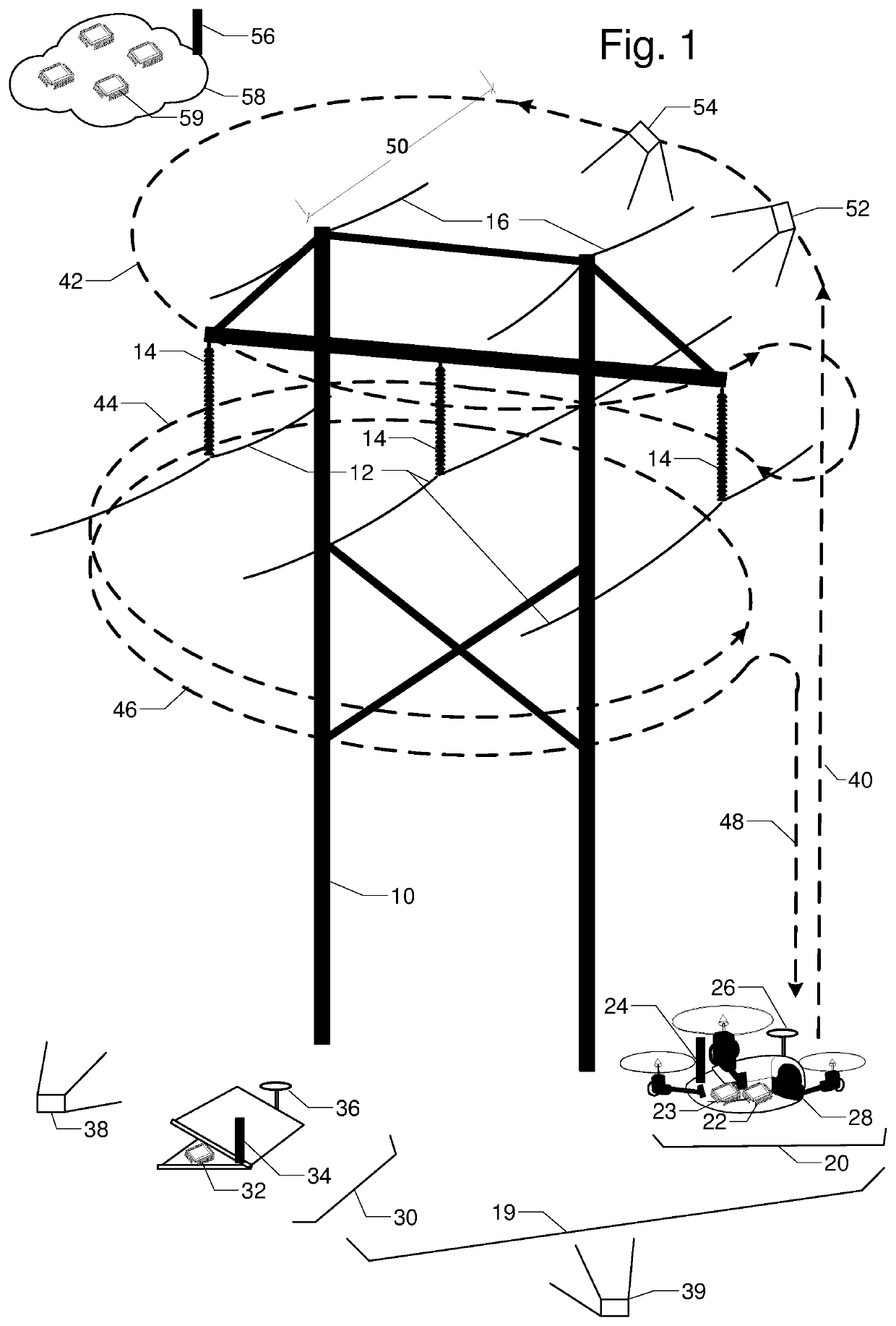
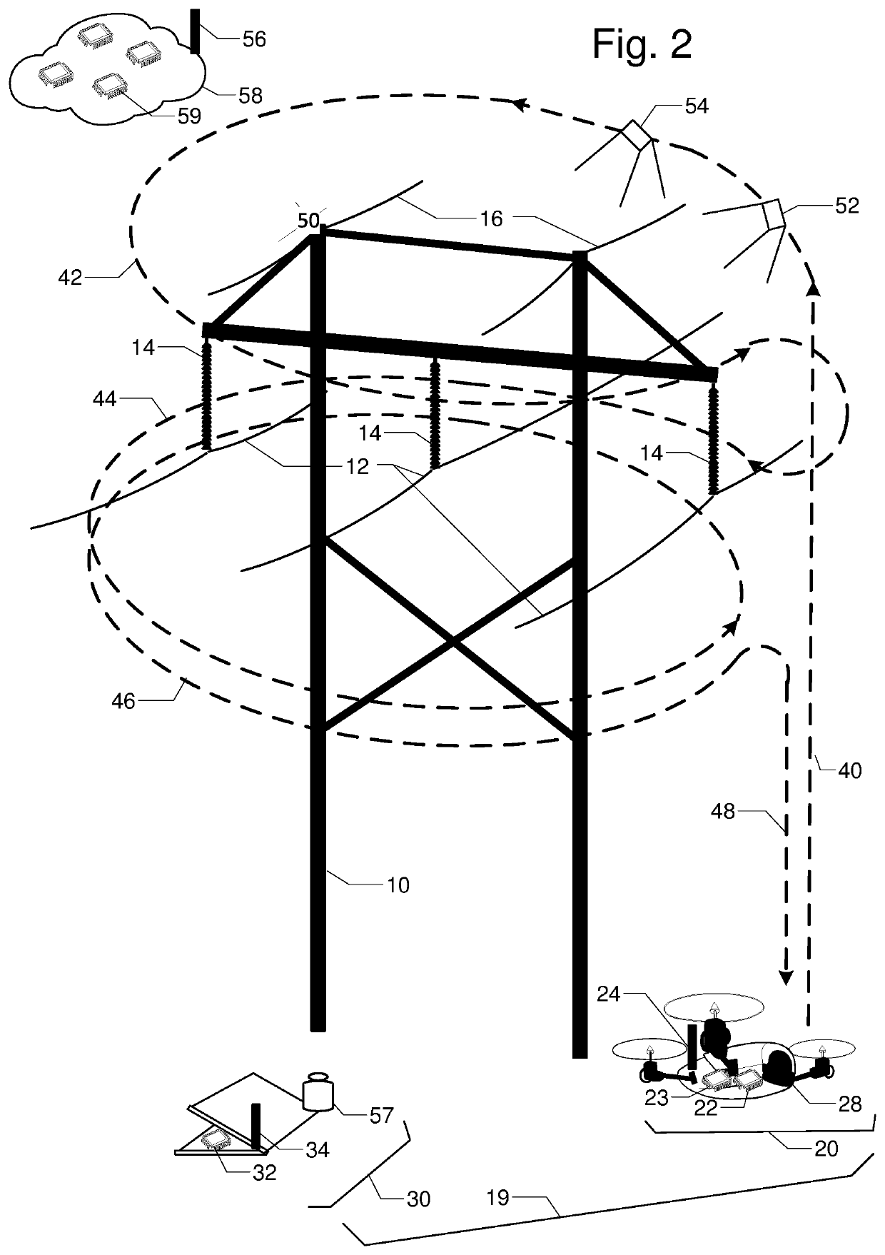
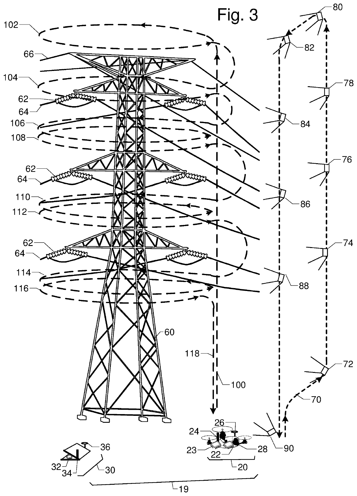
[0037]FIG. 1 is a perspective view of a transmission line H-tower 10 commonly used in single circuit transmission lines. Tower 10 supports insulators 14, which in turn support phase conductors 12. Tower 10 also supports shield wires 16 that reduce the impact of lightning strikes. The tower inspection system 19 is an unmanned aerial system (UAS), which includes a base station 30 and an unmanned aerial vehicle 20. Base station 30 has processer and memory 32, radio 34, and location base 36. UAV 20 has embedded processor and memory 22, inertial measurement unit (IMU) 23, radio 24, location rover 26, and camera 28. Orientation images 38 and 39 are taken from several vantage points. The inspection resolution and safety requirements determine standoff distance 50. Flight path with segments for ascent 40; loops 42, 44, and 46; and descent 48 maintains standoff distance 50 while provid...


PUM


Abstract

FIG. 1 is a perspective view of transmission tower 10, phase conductors 12, insulators 14, and shield wires 16. They are to be inspected by unmanned aerial vehicle UAV 20 with embedded processor and memory 22, radio 24, location rover 26, and camera 28. Base station 30 has processor and memory 32, radio 34, and location base 36. The relative location between UAV 20 and base station 30 can be accurately calculated by location base 36 and location rover 26 communicating over radios 24 and 34. Camera 28 on UAV 20 is first used to capture two or more orientation images 38 and 39 of tower 10; lines 12 and 16; and insulators 14 from different vantage points. Terrestrial or close-range photogrammetry techniques are used create a three dimensional model of tower 10; lines 12 and 16; and insulators 14. Based on inspection resolution and safety objectives, a standoff distance 50 is determined. Then a flight path with segments for ascent 40, one or more loops 42, 44, 46, and a descent 48 is designed to ensure full inspection coverage via inspection images like 52 and 54.

Description

CROSS-REFERENCE TO RELATED APPLICATIONS[0001]This application claims the benefit of provisional patent application Ser. No. 62 / 126,861 filed 2015 Mar. 2 by the present inventor.BACKGROUNDPrior Art[0002]Inspection, survey, or reconnaissance of towers and overhead lines aids in maintenance planning to prevent outages and deterioration. For example, problems in power transmission lines include:[0003]insulator contamination from salt, pollution, avian waste, or cumulative partial discharge;[0004]tower corrosion or avian nesting;[0005]lightning strike damage on shield wires or surge arrestors; and[0006]right-of-way incursion by vegetation or man-made structures.[0007]Ground-based inspection of towers, poles, utility corridors, and high voltage facilities such as substations is well known. For example, on high voltage transmission lines inspectors use a variety of inspection sensors such as binoculars, optical cameras with zoom lenses, thermal infrared cameras, solar blind ultraviolet cam...

Claims


Application Information

Patent Timeline
Patent Type & Authority Patents(United States)
IPC IPC(8): G01B21/04G06T17/05G05D1/10B64C39/02B64D47/08G01S17/89G01B21/00B64C19/00G05D1/00G06V20/13G06V20/17
CPCG05D1/101B64D47/08B64C39/024G06T17/05B64C2201/127B64C2201/141G05D1/0094H02G1/04G01C11/08G06V20/13G06V20/10G06V20/17B64U2101/30B64U2201/10B64U2101/26
Inventor VAN CRUYNINGEN, IZAK JAN
Owner VAN CRUYNINGEN IZAK JAN
Learn More