Supercharge Your Innovation With Domain-Expert AI Agents!

Microscope and method for obtaining a high dynamic range synthesized image of an object

a synthesized image and microscope technology, applied in the field of microscopes for obtaining high dynamic range synthesized images of objects, can solve the problems of low frame rate, low image brightness, and low image brightness, and achieve the effect of avoiding high requirements for image generation and simple structur

Active Publication Date: 2020-03-17
LEICA MICROSYSTEMS (SCHWEIZ) AG +1
View PDF18 Cites 0 Cited by
  • Summary
  • Abstract
  • Description
  • Claims
  • Application Information

AI Technical Summary

Benefits of technology

The invention aims to provide a microscope that can create a high dynamic range synthesized image of an object from multiple low dynamic range input images. The microscope is designed to have a simple structure to avoid high requirements for image generation.

Problems solved by technology

However, the known methods of varying the exposure time introduce some limitations for controlling the image brightness.
In particular, increasing the exposure time to obtain an HDR image can cause a drop in the frame rate.
Furthermore if the known method of increasing the sensitivity is used, chip noise can occur which results in brightness fluctuations on dark images.
This known method, however, has certain limitations.
In particular, using a laser for the illumination measurement makes illumination systems much more complicated.
Further, such systems are difficult to use for color imaging systems.
Further, such systems are more sensitive to the surface finishing and surface facet angle which will limit the application dramatically.
Further, the illumination of this known method uses a stripe pattern which will increase the difficulty of pixel fusion.
First, properly exposed areas and insufficiently exposed areas are divided (segmenting).
However, the prior art techniques will introduce the above-mentioned limitations for controlling the image brightness.
In particular, increasing the exposure time to obtain HDR images can cause a change or drop in the frame rate.

Method used


Image

  • Microscope and method for obtaining a high dynamic range synthesized image of an object
  • Microscope and method for obtaining a high dynamic range synthesized image of an object
  • Microscope and method for obtaining a high dynamic range synthesized image of an object

Examples


Embodiment Construction

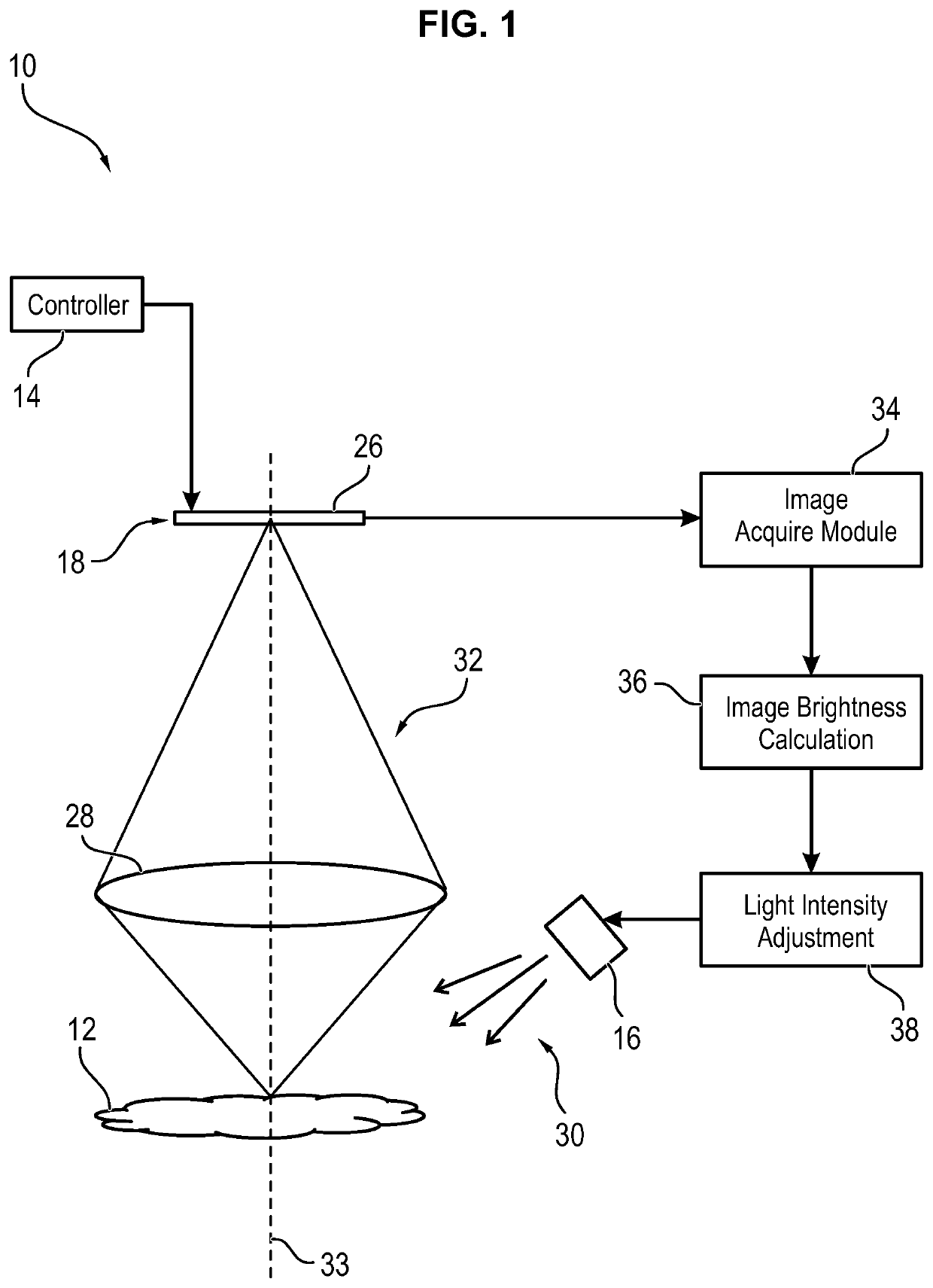
[0036]FIG. 1 shows a schematic illustration of a microscope 10 comprising a controller 14, an incoherent light source 16 and a recording device 18. As shown in FIG. 1, the recording device 18 comprises an image sensor 26 and an optical imaging system 28. The optical imaging system 28 is configured to image an object 12 onto the image sensor 26. The optical path is indicated by reference numeral 32. Further, the optical axis of the optical imaging system 28 is indicated by dashed line 33.

[0037]Referring to FIG. 1, the incoherent light source 16 is configured for illuminating the object 12 at different light intensity levels. The light emitted by the incoherent light source 16 is indicated by the arrows with reference numeral 30. The recording device 18 is configured for recording a plurality of low dynamic range input images of the object 12. In particular, each of the low dynamic range input images is recorded at a different light intensity level. Further referring to FIG. 1, the co...


PUM


Abstract

A microscope (10) for obtaining a high dynamic range synthesized image (21) of an object (12) from a plurality of low dynamic range input images (19) comprises a controller (14), an incoherent light source (16) for illuminating the object (12) at different light intensity levels, and a recording device (18) for recording the plurality of low dynamic range input images (19), wherein each of the low dynamic range input images (19) is recorded at a different light intensity level. The controller (14) is configured to control the recording device (18) such that during recording of the series of the low dynamic range images the recording parameters for obtaining the plurality of low dynamic range input images (19) are kept constant.

Description

CROSS-REFERENCE TO RELATED APPLICATIONS[0001]The present application is the U.S. national phase of International Application No. PCT / EP2014 / 071353 filed Oct. 6, 2014, the entire contents of which are incorporated herein by reference.FIELD OF THE INVENTION[0002]The invention relates to a microscope for obtaining a high dynamic range synthesized image of an object from a plurality of low dynamic range digital input images. Further, the invention relates to a method for obtaining a high dynamic range synthesized image of an object from a plurality of low dynamic range digital input images.BACKGROUND OF THE INVENTION[0003]Nowadays, many consumer and mobile phone cameras offer some sort of high dynamic range (HDR) mode to deal with a high contrast in the subject. HDR, as its name implies, is a method that aims to add more dynamic range to digital images, where dynamic range is the ratio of bright to dark in an image. To achieve HDR with limited hardware capability, instead of just taking...

Claims


Application Information

Patent Timeline
Patent Type & Authority Patents(United States)
IPC IPC(8): G02B21/36G02B21/06H04N5/235
CPCH04N5/2355G02B21/367G02B21/365G02B21/06H04N23/741
Inventor ZENG, ZHENG-DONGZOU, QING-SONGSCHMID, URS
Owner LEICA MICROSYSTEMS (SCHWEIZ) AG
Features
  • R&D
  • Intellectual Property
  • Life Sciences
  • Materials
  • Tech Scout
  • Unparalleled Data Quality
  • Higher Quality Content
  • 60% Fewer Hallucinations
Learn More