Apparatus for forming thin film

a technology of apparatus and thin film, applied in the direction of lining/internal coating, coating, metal material coating process, etc., can solve the problem of inferior performance for maintaining the quality of contents, and achieve the effect of enhancing the barrier characteristics of the entire container

Active Publication Date: 2020-04-07
KIRIN BREWERY CO LTD
View PDF19 Cites 0 Cited by
  • Summary
  • Abstract
  • Description
  • Claims
  • Application Information

AI Technical Summary

Benefits of technology

[0039](1) It becomes possible to perform film formation for only a short time period at the locations where the film formation time period could be limited from the point of view of thermal deformation, while with respect to the other locations it is possible to perform film formation sufficiently. As a result, it becomes simple and easy to enhance the barrier characteristics of the entire container.(2) It becomes simple and easy to form a film thickness distribution that is appropriate according to the intended purpose of the container and the required appearance quality of the container. Moreover, it becomes possible to implement coloration having graduations or the like.(3) In the prior art, as a countermeasure to prevent thermal deformation of the container, it was practiced only to start film formation after the heat generating element had been perfectly inserted into the container; but, according to the present invention, it becomes possible to reduce the cycle time, since the film formation can be started from the stage of inserting the heat generating element into the container.(4) Since it is possible always to keep the heat generating element in the vacuum state, accordingly it is possible to prevent deterioration of the heat generating element, so that the element's functionality for film formation does not decrease.(5) With respect to only the container chamber, vacuumization and open to atmosphere are implemented repeatedly, while the chamber for protection is always kept in the vacuum state. Due to this, it is only necessary to vacuumize the chamber for the container at a moment of film formation. Therefore it is possible to shorten the time period required during film formation for vacuumizing the entire vacuum chamber, so that it is possible to shorten the cycle time.(6) When, after having put the container into the chamber for the container, the chamber for the container has been vacuumized from atmospheric pressure and has reached a predetermined vacuum pressure, the communication between the container chamber and the chamber for protection having a lower vacuum pressure than the chamber for the container is established. Thereby, it is possible to lower the vacuum pressure in the chamber for the container. In other words, since the chamber for protection functions as a vacuum buffer, accordingly it is possible to shorten the time period required for vacuumizing the chamber for the container, so that it is possible to shorten the cycle time.(7) By raising and lowering a plurality of containers between the chamber for the container and the chamber for protection, it is possible to supply this plurality of unprocessed containers from the chamber for the container to the chamber for protection all at the same time and to perform film formation processing upon this plurality of containers simultaneously. Moreover, once they have been processed, it is also possible to take out the plurality of containers processed from the chamber for protection and transfer them to the chamber for the container.

Problems solved by technology

However, with respect to the plastic containers, as compared with the characteristics of metallic cans and glass bottles, as gas barrier performance is lower, ingress of oxygen into the interior of the containers and discharge of carbonic acid gas to the exterior of the containers may well occur, so that, in some cases, the performance for maintaining quality of the contents would be inferior.

Method used


Image

  • Apparatus for forming thin film
  • Apparatus for forming thin film
  • Apparatus for forming thin film

Examples


first embodiment

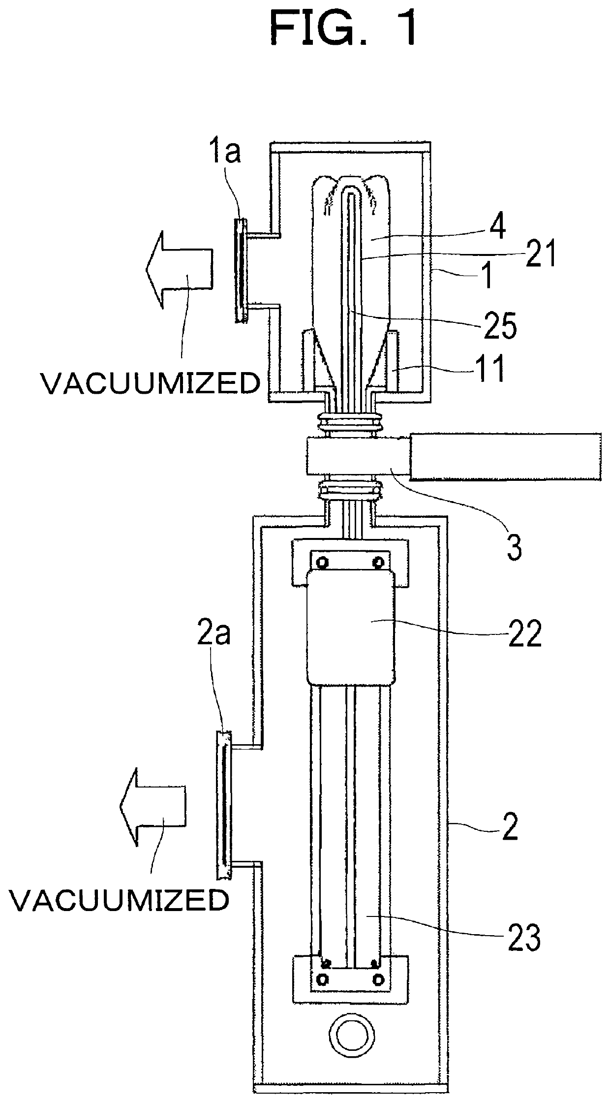
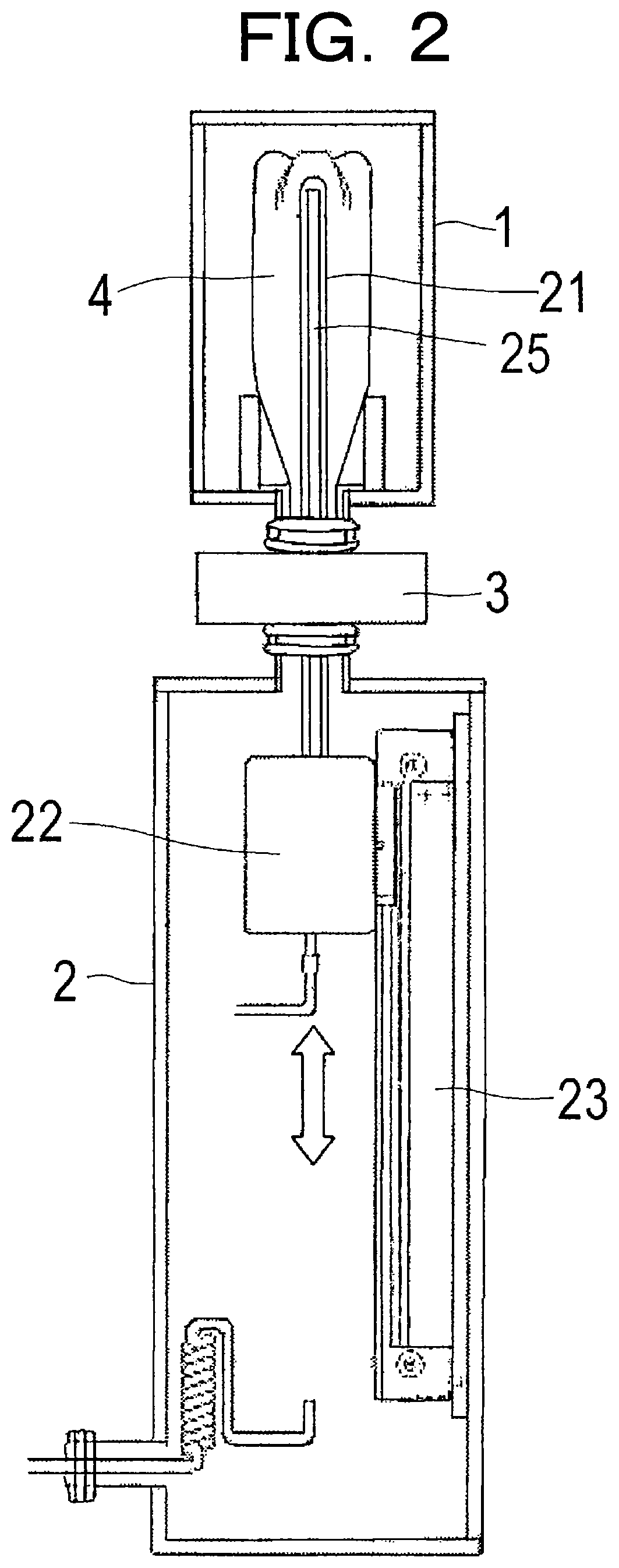
[0048]FIGS. 1 and 2 are figures showing the thin film formation apparatus according to the present invention.

[0049]FIG. 1 is a schematic sectional view showing the overall structure of the thin film formation apparatus according to a first embodiment of the present invention. And FIG. 2 is a side sectional view of the film formation apparatus shown in FIG. 1. As shown in FIGS. 1 and 2, the thin film formation apparatus of the present invention has a structure in which a vacuum chamber is divided into two parts: a film deposition chamber 1, and a heat generating element protection chamber 2. The film deposition chamber 1 is disposed above, while the heat generating element protection chamber 2 is disposed below. The volume of the film deposition chamber 1 is set to be less than the volume of the heat generating element protection chamber 2. The film deposition chamber 1 and the heat generating element protection chamber 2 are linked via a gate valve 3, which serves as a vacuum isolat...

second embodiment

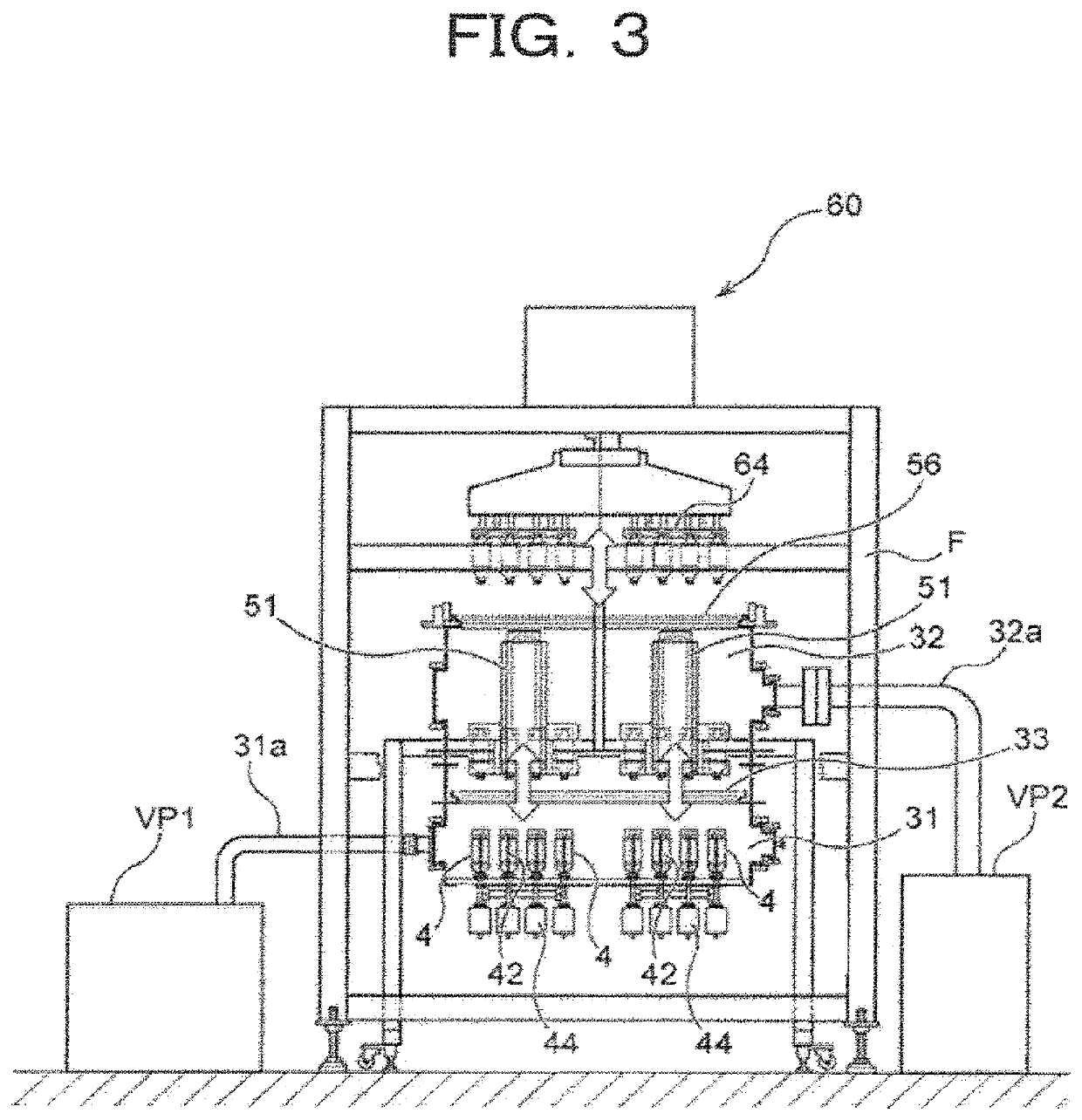
[0055]Next, the thin film formation apparatus according to the present invention will be explained with reference to FIGS. 3 through 5.

[0056]FIG. 3 is a schematic sectional view showing the overall structure of the thin film formation apparatus according to the second embodiment of the present invention. And FIG. 4 is a side sectional view of the film formation apparatus shown in FIG. 3. As shown in FIGS. 3 and 4, the thin film formation apparatus of the present invention comprises two chambers within a device frame F: a film deposition dedicated chamber 31, and a bottle in / out chamber 32. The film deposition dedicated chamber 31 is disposed below, while the bottle in / out chamber 32 is disposed above. The film deposition dedicated chamber 31 and the bottle in / out chamber 32 are connected via a gate valve 33, which serves as a vacuum isolation device.

[0057]The film deposition dedicated chamber 31 is linked via a link portion 31a to a vacuum pump VP1, which serves as a vacuum evacuati...


PUM

PropertyMeasurementUnit
distanceaaaaaaaaaa
temperatureaaaaaaaaaa
vacuumaaaaaaaaaa

Abstract

A film formation apparatus for forming a thin film having high gas barrier performance, such as a DLC (Diamond Like Carbon) film, a SiOx film, a SiOC film, a SiOCN film, a SiNx film, and an AlOx film, on an inner surface and / or an outer surface of a container such as a PET bottle. The film formation apparatus has: a vacuum chamber for forming, in a vacuum state, a film on a surface of a container using a heat generating element; a vacuum evacuation device for vacuumizing the vacuum chamber; and a relative shifting device for relatively shifting the container and the heat generating element in the vacuum chamber after the vacuumization of the vacuum chamber.

Description

TECHNICAL FIELD[0001]The present invention relates to an apparatus for forming thin film (a thin film formation apparatus) that forms a thin film whose gas barrier performance is high, such as a DLC (Diamond Like Carbon) film, an SiOx film, an SiOC film, an SiOCN film, an SiNx film, an AlOx film or the like, upon either the inner surface, or the outer surface, or both, of a container such as a polyethylene terephthalate bottle (a PET bottle) or the like.BACKGROUND ART[0002]While in the prior art hollow containers made from plastic which are light in weight, such as PET bottles, have been used for storing soft drinks and the like, the use of plastic containers in the food and drink field has spread rapidly due to their convenience and low cost, and, at the present time, PET bottles constitute quite a large proportion of all of the containers. However, with respect to the plastic containers, as compared with the characteristics of metallic cans and glass bottles, as gas barrier perfor...

Claims


Application Information

Patent Timeline
Patent Type & Authority Patents(United States)
IPC IPC(8): B65D23/02C23C16/34C23C16/40C23C16/27C23C16/448C23C16/54C23C16/455C23C16/46C23C16/04
CPCC23C16/403C23C16/27C23C16/401C23C16/4488C23C16/345B65D23/02C23C16/045C23C16/54C23C16/46C23C16/455
Inventor OOSHIMA, HIROYUKIFUJIMOTO, KEIICHITABUCHI, HIROYASUNAKAYA, MASAKI
Owner KIRIN BREWERY CO LTD
Why Eureka
Try Eureka