Measurement device and material tester

a measurement device and material testing technology, applied in the direction of material strength using tensile/compressive forces, instruments, material analysis, etc., can solve the problems of insufficient resolution, high resolution of load cell, and the inability of the amplifier device of the displacement meter to use the load cell, so as to improve the accuracy of the test force and elongation value measured during material testing, improve the accuracy of the measurement of the gain on the sensor amplifier side, and improve the accuracy of the measured material testing

Active Publication Date: 2020-06-30
SHIMADZU CORP
View PDF14 Cites 0 Cited by
  • Summary
  • Abstract
  • Description
  • Claims
  • Application Information

AI Technical Summary

Benefits of technology

[0019]The nonvolatile memory storing the information on the connected detector and the resistor determining the gain of the instrumentation amplifier are placed in the cable unit and the resistor in the cable unit determines the gain of the instrumentation amplifier such that the magnitude of the signal that the sensor amplifier receives from the detector becomes a magnitude optimal for an analog circuit in the sensor amplifier. Accordingly, the amplifier can be used at an optimal gain for every detector electrically connectable to the sensor amplifier.
[0020]The electrical calibration circuit is provided in the cable unit, and thus so-called shunt calibration can be performed for any connected detector. In other words, with the electrical calibration circuit in the cable unit, electrical calibration can be performed even with respect to detectors that could not be electrically calibrated in the past. Furthermore, the input from the detector side can be disconnected by the switch, and thus a stationary state on the detector side does not have to be confirmed during electrical calibration unlike in the past. Accordingly, electrical calibration can be performed regardless of the state on the detector side. Therefore, the gain on the sensor amplifier side can be accurately adjusted.
[0021]The measuring device with which the amplifier can be used at an optimal gain is provided, and thus the accuracy of a measured material testing value can be improved along with resolution.
[0022]The amplifier can be used at an optimal amplifier gain at which the capabilities of the load cell and the displacement meter can be appropriately demonstrated, and thus the accuracy of test force and elongation values measured during material testing can be improved.

Problems solved by technology

In addition, in a strain gauge type displacement meter and a load cell that use the same measurement method despite different physical quantities to be measured, the load cell requires high resolution, and thus resolution is insufficient even when the load cell is connected to an amplifier device for a displacement meter as in Patent Document 2.
Accordingly, the amplifier device for a displacement meter cannot be used for the load cell.
Furthermore, the amplifier device for a displacement meter disclosed in Patent Document 2, which responds to strain gauge and differential transformer type displacement meters, is too sensitive and cannot be used as it is with regard to a potentiometer type displacement meter.
No electrical measuring circuit calibration, however, can be performed even when the differential transformer type displacement meter is connected to the amplifier by means of the cable.
Although Patent Document 4 has proposed a circuit that is capable of performing electrical calibration in a case where a differential transformer type displacement meter is connected, this technique uses amplifier side impedance as well during calibration, and thus has problems such as the necessity of a circuit therefor in an earlier stage than an instrumentation amplifier, the necessity of a change in cable side impedance reflecting the type and full scale of the differential transformer type displacement meter, and the necessity of the same differential transformer iron core position during calibration.

Method used


Image

  • Measurement device and material tester
  • Measurement device and material tester
  • Measurement device and material tester

Examples


Embodiment Construction

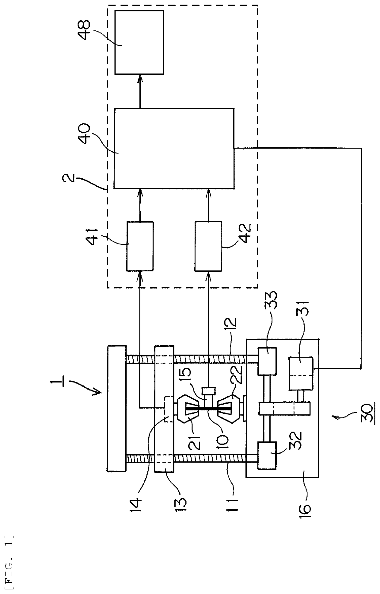
[0032]Hereinafter, an embodiment of the invention will be described with reference to accompanying drawings. FIG. 1 is a schematic diagram of a material testing machine.

[0033]A testing machine main body 1 and a control device 2 constitute this material testing machine. The testing machine main body 1 is provided with a table 16, a pair of screw rods 11 and 12 rotatably standing on the table 16 while facing a vertical direction, a crosshead 13 movable along the screw rods 11 and 12, a load mechanism 30 for giving a load to a test piece 10 as a measurement object by moving the crosshead 13, and a load cell 14 and a displacement meter 15 as detectors converting a change in physical quantity in the test piece 10 into an electric signal.

[0034]The crosshead 13 is connected to the pair of screw rods 11 and 12 via nuts (ball nuts, not illustrated). Worm reducers 32 and 33 of the load mechanism 30 are connected to the lower end portions of the screw rods 11 and 12, respectively. The worm red...


PUM

PropertyMeasurementUnit
physical quantityaaaaaaaaaa
forceaaaaaaaaaa
displacement meteraaaaaaaaaa

Abstract

Once a sensor amplifier side connector of a cable unit for interconnecting a detector and a sensor amplifier is connected to the sensor amplifier, a gain resistor on the cable unit side and an instrumentation amplifier of the sensor amplifier are interconnected and the gain of the instrumentation amplifier is determined. As a result, the gain of the instrumentation amplifier is determined such that the magnitude of a signal that the sensor amplifier receives from the detector becomes a magnitude optimal for an analog circuit in the sensor amplifier.

Description

FIELD[0001]The present invention relates to a measuring device and a material testing machine provided with a detector converting a physical quantity into an electric signal.BACKGROUND[0002]Arranged in a material testing machine performing material testing are a load mechanism giving a test load to a test piece and a plurality of detectors converting a physical quantity into an electric signal, examples of the detectors including a test force detector measuring a test force given to the test piece by the load mechanism and a displacement meter detecting displacement generated in the test piece. A physical quantity measuring system for material testing is configured by the detectors being connected to a testing machine controller controlling the entire material testing machine via an amplifier (see Patent Document 1).[0003]In the related art, sensor amplifiers should be individually prepared, in view of the difference between the physical quantity measurement methods of the detectors...

Claims


Application Information

Patent Timeline
Patent Type & Authority Patents(United States)
IPC IPC(8): G01N3/00G01N3/08G01N3/06H03F3/45G01N3/62G01B7/16
CPCG01N3/066H03F3/45G01N3/06G01N3/08G01N3/62H03F2200/261G01B7/16
Inventor TSUJI, HIROSHI
Owner SHIMADZU CORP
Why Eureka
Try Eureka