
Data transition in highly parallel database management system

a database management system and data transfer technology, applied in database management systems, memory allocation/allocation/relocation, relational database management systems, etc., can solve the problems of not meeting the demands of certain users, increasing the amount of data generated, and other types of traditional database systems, so as to improve the system performance, reduce the cost, and increase the utilization of storage drives.

Active Publication Date: 2020-07-14
OCIENT INC
View PDF59 Cites 0 Cited by
  • Summary
  • Abstract
  • Description
  • Claims
  • Application Information

AI Technical Summary

Benefits of technology

This patent describes a database system that is designed to manage large volumes of data with low latency and high performance. It uses a massively parallel system with multiple servers and storage devices to handle data in rows and minimize rewrites on solid state drives. It achieves higher utilization of storage drives and reduces cost by panning memory buffers and optimizing data placement. The database system directly interfaces with storage device drivers in computer programming languages such as C++, improving performance and utilization. Overall, this patent presents a technical solution for managing large data volumes efficiently.

Problems solved by technology

However, relational database management systems, and other types of traditional database systems, no longer meet the demands of certain users as Internet and other technologies produce and consume dramatically more data in recent years.
In particular, larger and larger amount of data are generated as each day goes by.
Traditional database management systems cannot meet such a demand.
These efforts still fall short for the new challenges.
For example, Bigtable and DynamoDB are not optimized for data with extremely high read-write ratios, are sparse and thus not storage efficient, still rely on conventional infrastructure, and cannot directly access storage devices for optimal performance.

Method used

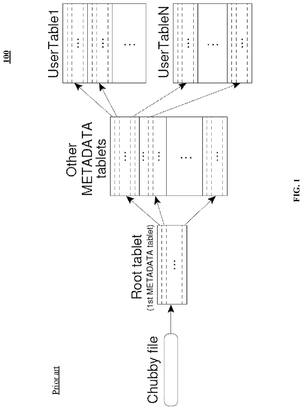
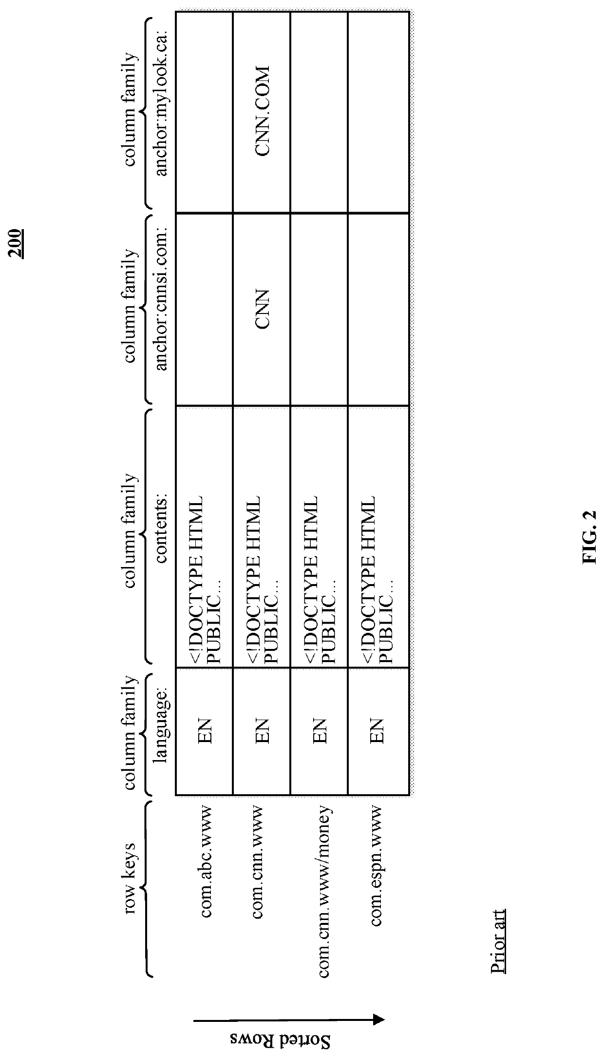

Image

  • Data transition in highly parallel database management system
  • Data transition in highly parallel database management system
  • Data transition in highly parallel database management system

Examples


Embodiment Construction

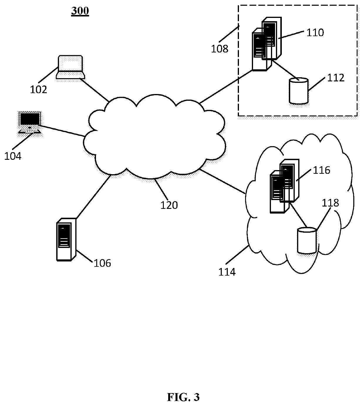
[0082]Turning to the Figures and to FIG. 3 in particular, a communication system for managing and serving a large volume of data is shown and generally indicated at 300. The illustrative system 300 includes a client computer 102, a client computer 104, a third party server system 106, and a database management system 108. The client computers 102-104 and the third party server 106 communicates with the database management system 108 over a wide network 120, such as the Internet. The database management system 108 includes a database server 110 and database system 112. The database server 110 interfaces with the client computers 102-104 and the third party server 106, and interacts with the database system 112. For example, the client computer 104 and / or the server 106 accesses the database server 110 to request data stored in the database system 112. The requested data is read from the database system 112 and returned to the data requestor. The database server 110 can also be reques...


PUM


Abstract

A massively parallel database management system includes an index store and a payload store including a set of storage systems of different temperatures. Both the stores each include a list of clusters. Each cluster includes a set of nodes with storage devices forming a group of segments. Nodes and clusters are connected over high speed links. The list of clusters within the payload store includes clusters of different temperatures. The payload store transitions data of a segment group from a higher temperature to a segment group in a lower temperature cluster in parallel. A node moves data of a segment in the higher temperature cluster to a corresponding node's segment in the lower temperature cluster. Once the data is written in the destination segment in the lower temperature cluster, the source segment is freed to store other data. The temperatures include blazing, hot, warm and cold.

Description

CROSS REFERENCE TO RELATED APPLICATIONS[0001]This application claims the benefit and priority of U.S. Patent Application No. 62 / 403,231, entitled “HIGHLY PARALLEL DATABASE MANAGEMENT SYSTEM,” filed Oct. 3, 2016, which is hereby incorporated by reference in its entirety. This application also claims the benefit and priority of U.S. Patent Application No. 62 / 403,328, entitled “APPLICATION DIRECT ACCESS TO NETWORK RDMA MEMORY,” filed Oct. 3, 2016, which is hereby incorporated by reference in its entirety. This application is related to U.S. patent application Ser. No. 15 / 722,900, entitled “RANDOMIZED DATA DISTRIBUTION IN HIGHLY PARALLEL DATABASE MANAGEMENT SYSTEM,” filed Oct. 2, 2017, which is hereby incorporated by reference. This application is related to U.S. patent application Ser. No. 15 / 722,687, entitled “DATABASE SYSTEM UTILIZING FORCED MEMORY ALIGNED ACCESSES,” filed Oct. 2, 2017, which is hereby incorporated by reference. This application is also related to U.S. patent applica...

Claims


Application Information

Patent Timeline
Patent Type & Authority Patents(United States)
IPC IPC(8): G06F16/00H04L29/08G06F15/173G06F16/23G06F16/28G06F16/22G06F16/27G06F12/02G06F13/16G06F16/25G06F13/28G06F13/42G06F3/06
CPCG06F16/2358G06F16/2365G06F13/4282G06F12/0238G06F13/1673G06F16/285G06F16/25G06F15/17331H04L67/1097G06F16/22G06F13/28H04L67/2842G06F16/27G06F3/067G06F3/0656G06F2213/0026G06F2213/0032G06F2212/202H04L67/568
Inventor KONDILES, GEORGESTARR, RHETT COLINJABLONSKI, JOSEPH
Owner OCIENT INC
Learn More