Flexible system integration to improve thermal properties

a flexible system and thermal insulation technology, applied in the direction of semiconductor devices, semiconductor/solid-state device details, electrical apparatus, etc., can solve the problems of difficult heat removal, soc die shrinkage, complex heat removal, etc., to improve the overall system performance, and improve the effect of thermal insulation performan

Active Publication Date: 2020-07-14
APPLE INC
View PDF13 Cites 1 Cited by
  • Summary
  • Abstract
  • Description
  • Claims
  • Application Information

AI Technical Summary

Benefits of technology

[0004]In an embodiment, an apparatus comprises an interposer to which multiple integrated circuits are coupled. The ICs may include processors (e.g. graphics processing units (GPUs), central processing units (CPUs), etc.). Other ICs may include portions of non-processor functionality that may have previously been integrated with the processors on an SOC and / or other chips / devices such as field programmable gate arrays (FPGAs) and / or analog ICs. With the separation of the SOC functionality into multiple into ICs, the ICs may be arranged on the interposer to spread out the potentially high power ICs (e.g. processors) and lower power ICs, interleaving the low power ICs with the high power ICs, in some embodiments. Thus, the heat may be generated over a larger area and may be more readily dissipated, in some embodiments. The effective thermal mass around such “hot spots” may increase, slowing the temperature rise during operation at more optimal power / performance states and thus allowing longer operation in such states. Such implementations may be effective, e.g., in cases where the high power ICs are computationally-intensive power consumers like processors, as compared to communication-intensive power consumers.
[0006]In some embodiments, the above effects may permit the ICs to operate in higher performance state for longer, since the heat generated may be more readily dissipated. Even though the area consumed by the interposer may be greater than a corresponding single chip SOC, the performance of the overall system may be better. Such embodiments may be helpful to systems with intermittent high performance needs, which may generate rapid local heat changes for a short period of time. The PCM may absorb this heat, and if operating the system in short higher performance states results in improved system energy relative to operating the system in lower performance states for longer times, an overall energy efficiency may be gained.
[0007]In some embodiments, the interposer is coupled to a main logic board (MLB) which is formed on a light guide for a display screen of the device that includes the interposer. This configuration may reduce the height of the overall assembly, in an embodiment. Additionally, yield may be improved over a single SOC solution, since a defective IC can be discarded before assembly on the interposer, whereas the single SOC would be discarded for any defect in any of the integrated functionality.

Problems solved by technology

However, the shrinking of so much functionality onto one SOC die also has drawbacks.
Removing the heat can be challenging.
Particularly, in a handheld device, heat removal is complicated by a lack of cooling fans and other air-circulation mechanisms typically used in laptops, desktops, and servers.
Heat removal is further complicated by the fact that heat buildup is very noticeable in a hand held device, and can be uncomfortable for the user.
The difficulties in removing heat can also limit the amount of time that the SOC (or portions of the SOC, such as the processors) can operate in the highest performance states.
Additionally, keeping the SOC powered up for computation incurs a number of overhead factors that consume power (e.g. the phase locked loop (PLL) that generates clocks in the SOC, various general purpose I / O pins and other serializer / deserializer (SERDES) links remain active, etc.
So, keeping the SOC powered up for long periods of time in a lower performance state, with higher power overhead may be less efficient than “sprinting:” Operating at high performance / power state (or “optimal” power / performance state) for short periods of time to complete tasks, and then entering low power modes as quickly as possible to save power.
Thus, high performance circuits may generally have higher leakage currents in idle state, unless power gated or the power supply voltage magnitude is reduced.

Method used


Image

  • Flexible system integration to improve thermal properties
  • Flexible system integration to improve thermal properties
  • Flexible system integration to improve thermal properties

Examples


Embodiment Construction

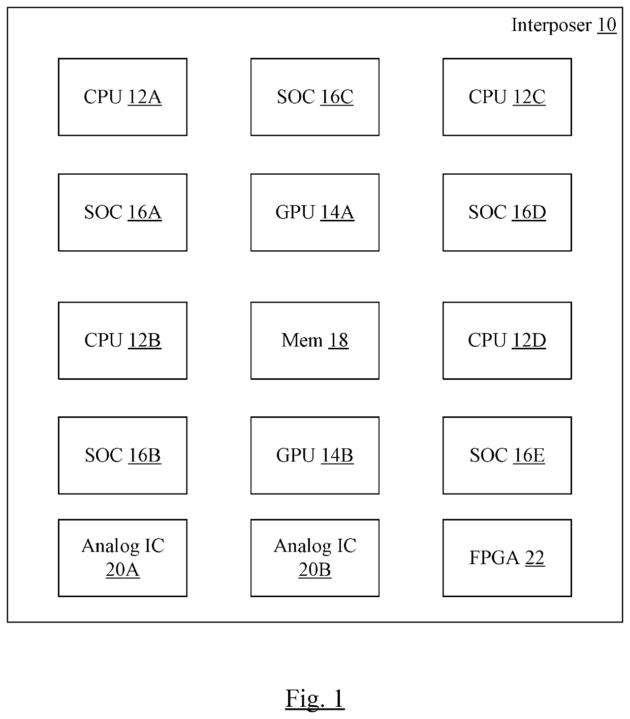
[0021]Turning now to FIG. 1, a block diagram of one embodiment of an interposer 10 is shown with various integrated circuits attached to a surface thereof. In the illustrated embodiment, the integrated circuits include CPUs 12A-12D, GPUs 14A-14B, various other portions of an SOC in discrete ICs 16A-16E, a memory 18, one or more analog ICs 20A-20B, and one or more FPGAs 22. The memory 18 may be an integrated circuit as well, or may be multiple integrated circuits in a stack, in various embodiments.

[0022]The CPUs 12A-12D and GPUs 14A-14B may generally be capable of significantly higher power consumption, at least in some performance states, than other ones of the integrated circuits 16A-16E and 18. Generally, processors of various types may be capable of higher power consumption than other integrated circuit components. The higher-power-consuming components (e.g. CPUs 12A-12D and GPUs 14A-14B) may physically spaced out over the surface of the interposer 10, locating the high heat gene...


PUM


Abstract

In an embodiment, an interposer includes multiple integrated circuits coupled thereto. The integrated circuits may include processors and non-processor functionality that may have previously been integrated with the processors on an SOC. By separating the functionality into multiple integrated circuits, the integrated circuits may be arranged on the interposer to spread out the potentially high power ICs and lower power ICs, interleaving them. In other embodiments, instances of the integrated circuits (e.g. processors) from different manufacturing process conditions may be selected to allow a mix of high performance, high power density integrated circuits and lower performance, low power density integrated circuits. In an embodiment, a phase change material may be in contact with the integrated circuits, providing a local reservoir to absorb heat. In an embodiment, a battery or display components may increase thermal mass and allow longer optimal performance state operation.

Description

BACKGROUNDTechnical Field[0001]Embodiments described herein are related to electronic devices and the integrated circuits used therein.Description of the Related Art[0002]Over time, more functionality has been integrated into system on a chip (SOC) integrated circuits (ICs). The increasing integration permits smaller device form factors, and in some cases improved power efficiency. However, the shrinking of so much functionality onto one SOC die also has drawbacks. For example, when the SOC is operating in a high performance mode (high power supply voltage and high clock frequency), a significant amount of heat can be generated in a very small area. Removing the heat can be challenging. Particularly, in a handheld device, heat removal is complicated by a lack of cooling fans and other air-circulation mechanisms typically used in laptops, desktops, and servers. Heat removal is further complicated by the fact that heat buildup is very noticeable in a hand held device, and can be uncom...

Claims


Application Information

Patent Timeline
Patent Type & Authority Patents(United States)
IPC IPC(8): H01L23/367H01L25/065H01L23/538H01L23/427H01L23/28H01L23/13H01L23/34H01L23/00
CPCH01L25/0652H01L23/5385H01L23/13H01L23/28H01L23/427H01L2224/16145H01L2924/15311H01L2924/1432H01L2224/08145H01L2924/12044H01L2224/80896H01L2224/16227H01L2924/1431H01L2924/1434H01L24/13H01L24/17H01L2224/131H01L2224/80895H01L2924/12041H01L2924/15312H01L24/08H01L24/16H01L24/80H01L2924/014H01L2924/00014
Inventor DABRAL, SANJAY
Owner APPLE INC
Why Eureka
Try Eureka