Impairment compensation techniques for high performance coherent optical transceivers

a technology of interference compensation and coherent optical transmission, which is applied in the field of optical communication improvement methods and devices, can solve the problems that the phase and gain imbalance of the modulator (tx) cannot be completely compensated at the receiver

Active Publication Date: 2020-07-14
MARVELL ASIA PTE LTD
View PDF19 Cites 2 Cited by
  • Summary
  • Abstract
  • Description
  • Claims
  • Application Information

AI Technical Summary

Problems solved by technology

Furthermore, we demonstrate that the phase and gain imbalance of the modulator (Tx) cannot be completely compensated at the receiver without amplifying the channel noise.

Method used


Image

  • Impairment compensation techniques for high performance coherent optical transceivers
  • Impairment compensation techniques for high performance coherent optical transceivers
  • Impairment compensation techniques for high performance coherent optical transceivers

Examples


case 1

A. Impact of Quadrature Error (τ=0)

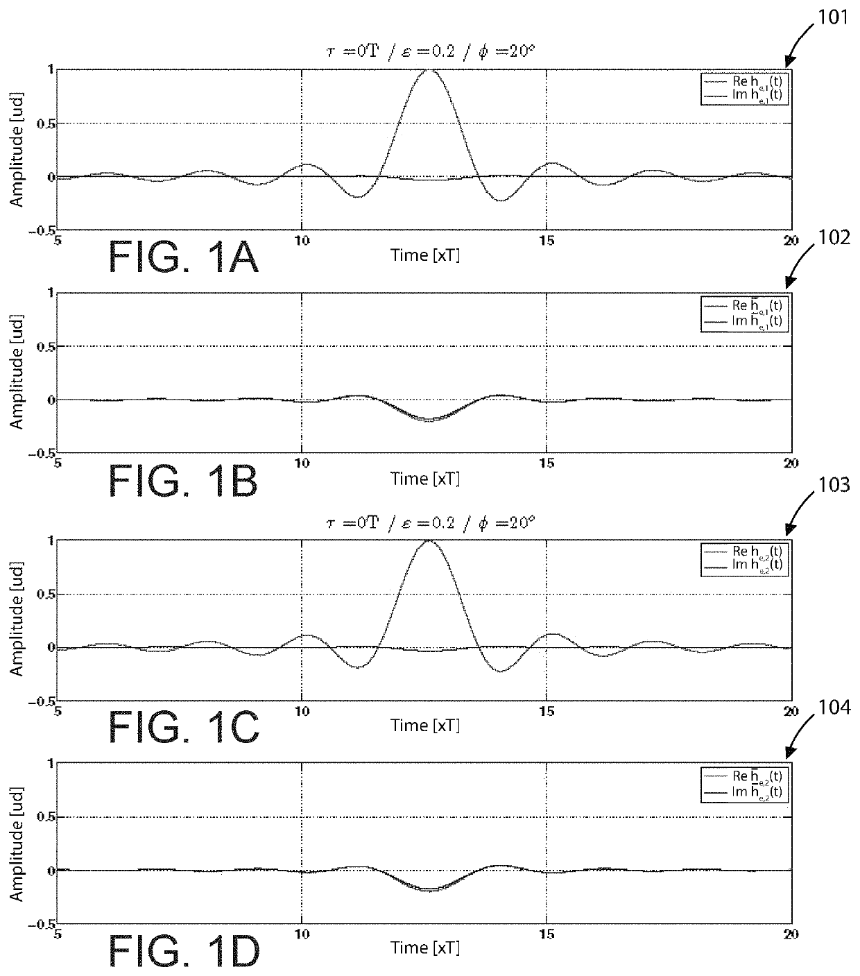
[0052]In the absence of I / Q skew (i.e., τ=0), the following can be determined:

f(t)=αδ(t)

f(t)=βδ(t)

Since f(t)e±jωct=αδ(t)e±jωct=αδ(t) and f(t)e±jωct=βδ(t)e±jωct=βδ(t), the following can be determined:

he,1(t)=he,2(t)=αg(t)

he,1(t)=he,2(t)=βg(t)

[0053]FIGS. 1A-1D are sample graphs illustrating simulation channel responses according to examples of the present invention. More specifically, graphs 101-104 show simulation responses under the following criteria: τ=0 T, ∈=0.2, and ϕ=20°. These results confirm the predictions previously discussed.

[0054]Next, we evaluate the impact and compensation of the quadrature error on the receiver. Assuming that g(t) is an ISI-free pulse, we can verify that the baud rate samples of the signals for a same polarization of both subcarriers result as follows:

r1,x(n)=ααn,1+βαn,2*  (27)

r2,x(n)=ααn,2+βαn,1*  (28)

Note that an,1 and an,2* can be detected (instead of an,2) by considering the equivalent system as follows:

r1,x(n)=α...

case 2

B. Impact of IQ Skew (∈=0 and ϕ=0)

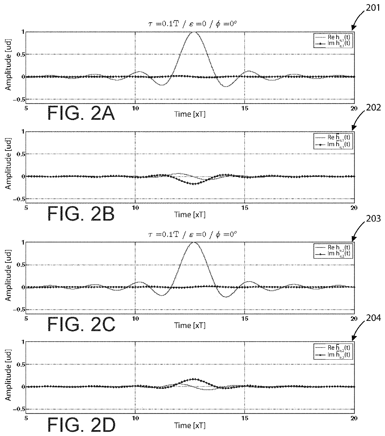
[0065]In this case, we get the following:

[0066]f⁡(t)=12⁡[δ⁡(t+τ / 2)+δ⁡(t-τ / 2)]f_⁡(t)=12⁡[δ⁡(t+τ / 2)-δ⁡(t-τ / 2)]

Taking into account that g(t) is a real pulse, we obtain the following:

[0067]he,1⁡(t)=12⁡[ej⁢⁢ωc⁢τ / 2⁢g⁡(t+τ / 2)+e-j⁢⁢ω⁢c⁢τ / 2⁢g⁡(t-τ / 2)]he,2⁡(t)=12⁡[e-j⁢⁢ωc⁢τ / 2⁢g⁡(t+τ / 2)+ej⁢⁢ω⁢c⁢τ / 2⁢g⁡(t-τ / 2)]=he,1*⁡(t)h_e,1⁡(t)=12⁡[e-j⁢⁢ωc⁢τ / 2⁢g⁡(t+τ / 2)-ej⁢⁢ω⁢c⁢τ / 2⁢g⁡(t-τ / 2)]h_e,2⁡(t)=12⁡[ej⁢⁢ωc⁢τ / 2⁢g⁡(t+τ / 2)-e-j⁢⁢ω⁢c⁢τ / 2⁢g⁡(t-τ / 2)]=h_e,1*⁡(t)

When τ is small (e.g., |τ|<0.2 T), the result is the following:

he,1(t)=he,2(t)≈cos(ωcτ / 2)g(t)  (35)

he,1(t)=he,2(t)≈j sin(ωcτ / 2)g(t)  (36)

[0068]FIGS. 2A-2D are sample graphs illustrating simulation channel responses according to examples of the present invention. More specifically, graphs 201-204 show simulation responses under the following criteria: τ=0.1 T, ∈=0, and ϕ=0. Again, these results confirm the predictions previously discussed.

[0069]In order to provide a simple approach to determining the impact of Tx I / Q skew...

case 3

C. Impact of I / Q Skew and Quadrature Error (∈=0 and ϕ=0)

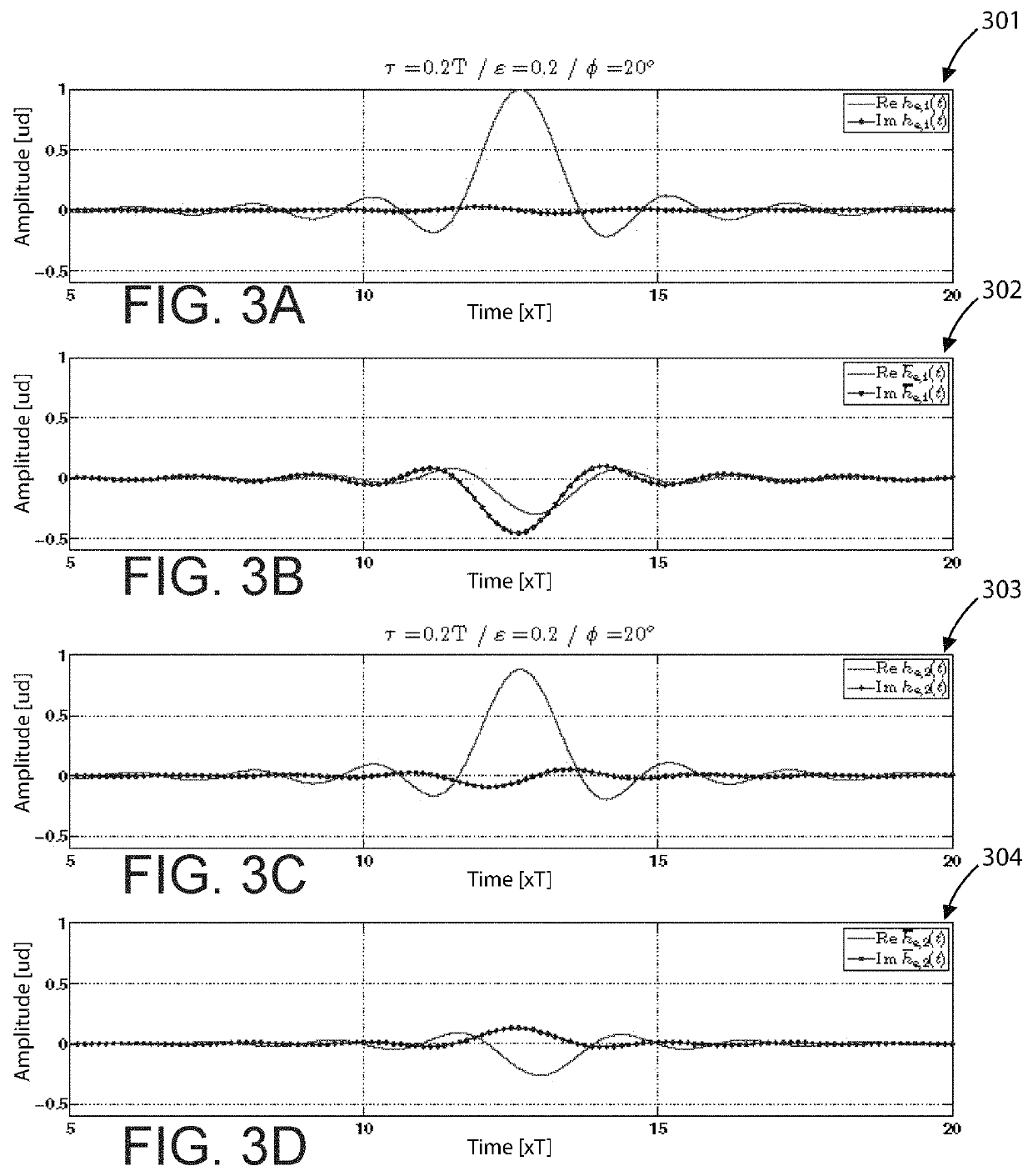
[0073]Similar to the above method, it is possible to show the following:

[0074]he,1⁡(t)=(α+β)2⁢ej⁢⁢ωc⁢τ / 2⁢g⁡(t+τ / 2)+(α-β)2⁢e-j⁢⁢ωc⁢τ / 2⁢g⁡(t-τ / 2)he,2⁡(t)=(α+β)2⁢e-j⁢⁢ωc⁢τ / 2⁢g⁡(t+τ / 2)+(α-β)2⁢ej⁢⁢ωc⁢τ / 2⁢g⁡(t-τ / 2)h_e,1⁡(t)=(α+β)2⁢e-j⁢⁢ωc⁢τ / 2⁢g⁡(t+τ / 2)-(α-β)2⁢ej⁢⁢ωc⁢τ / 2⁢g⁡(t-τ / 2)h_e,2⁡(t)=(α+β)2⁢ej⁢⁢ωc⁢τ / 2⁢g⁡(t+τ / 2)-(α-β)2⁢e-j⁢⁢ωc⁢τ / 2⁢g⁡(t-τ / 2)

Since α and β are complex numbers in general, note that |he,1(t)|≠|he,2(t)| and |he,1(t)|≠|he,2(t)|.

[0075]FIGS. 3A-3D are sample graphs illustrating simulation channel responses according to examples of the present invention. More specifically, graphs 301-304 show equivalent baseband channel responses from simulations under the following criteria: τ=0.2 T, ∈=0.2, and ϕ=20°. Unlike the previous examples, there are important differences between the magnitude of the responses he,1(t) and he,2 (t). This shows that the impact of the combined effects of quadrature error and I / Q skew on performance s...


PUM


Abstract

A method and structure for compensation techniques in coherent optical receivers. The present invention provides a coherent optical receiver with an improved 8×8 adaptive MIMO (Multiple Input, Multiple Output) equalizer configured within a digital signal processor (DSP) to compensate the effects of transmitter I / Q skew in subcarrier multiplexing (SCM) schemes. The 8×8 MIMO equalizer can be configured such that each of the 8 outputs is electrically coupled to 3 of 8 inputs, wherein each of the input-output couplings is configured as a filter. The method includes compensating for impairments to the digital conversion of an optical input signal via the 8×8 MIMO equalizer following other signal processing steps, such as chromatic dispersion (CD) / polarization-mode dispersion (PMD) compensation, carrier recovery, timing synchronization, and cycle slip correction.

Description

CROSS-REFERENCES TO RELATED APPLICATIONS[0001]The present application claims priority to an incorporates by reference, for all purposes, the following U.S. provisional patent application: U.S. Provisional App. No. 62 / 621,521, filed on Jan. 24, 2018.BACKGROUND OF THE INVENTION[0002]The present invention relates to communication systems and integrated circuit (IC) devices. More particularly, the present invention provides for improved methods and devices for optical communication.[0003]Over the last few decades, the use of communication networks exploded. In the early days Internet, popular applications were limited to emails, bulletin board, and mostly informational and text-based web page surfing, and the amount of data transferred was usually relatively small. Today, Internet and mobile applications demand a huge amount of bandwidth for transferring photo, video, music, and other multimedia files. For example, a social network like Facebook processes more than 500 TB of data daily....

Claims


Application Information

Patent Timeline
Patent Type & Authority Patents(United States)
IPC IPC(8): H04B10/61H04B10/40H04J14/02
CPCH04B10/6161H04B10/40H04B10/6162H04J14/0298H04B10/616H04L27/34H04L1/0042H04L1/0047H03M7/28H03M7/14H03M7/008H04B10/516H04L27/2275H04L27/3836
Inventor HUEDA, MARIO RAFAELCORREA LUST, JOSÉ L.MORERO, DAMIAN ALFONSO
Owner MARVELL ASIA PTE LTD
Why Eureka
Try Eureka