Method for operating a motor vehicle, control unit for a drive system, and drive system

a technology of control unit and motor vehicle, which is applied in the direction of electric vehicle charging technology, mechanical equipment, transportation and packaging, etc., can solve the problems of high computation expenditure of control unit, increase the complexity of control strategy for controlling, and increase the error-proneness of additional energy sources, so as to achieve low error-proneness and high co2-economization potential

Active Publication Date: 2020-08-11
ROBERT BOSCH GMBH
View PDF17 Cites 3 Cited by
  • Summary
  • Abstract
  • Description
  • Claims
  • Application Information

AI Technical Summary

Benefits of technology

[0015]In particular, information that may be ascertained on site, which is obtainable comparatively simply for the current point in time, but which would be predictively determinable only at great expense, may be used quasi in real time. Furthermore, it is possible to increase the accuracy of the required setpoint state of charge curve in such a way that it is close to the optimized curve with respect to the CO2 emission. At the same time, it is possible to reduce the demand for computing power of the control unit and / or the latter's computing power may be better utilized in comparison to the related art.
[0038]This makes it possible to perform the method in a particularly robust manner. In particular, it is particularly well possible to implement a blended-mode strategy effectively and efficiently with the aid of the setpoint state of charge regulation of the ECMS and predictive information. Analyses of an ECMS operating strategy in diverse driving cycles have shown that it is possible to achieve the respectively best setpoint state of charge curve in most cases with high accuracy by correcting the linear setpoint state of charge curve by the remaining potential and kinetic energy of the motor vehicle with respect to the destination.

Problems solved by technology

It has furthermore become clear that in an PHEV the supply from an additional energy source increases the complexity of the control strategy for controlling the energy management that is to be used in a PHEV.
The calculation of a setpoint curve that is as efficient and CO2-economizing as possible normally requires a high computation expenditure for the control unit (ECU) of the vehicle.

Method used


Image

  • Method for operating a motor vehicle, control unit for a drive system, and drive system
  • Method for operating a motor vehicle, control unit for a drive system, and drive system
  • Method for operating a motor vehicle, control unit for a drive system, and drive system

Examples


Embodiment Construction

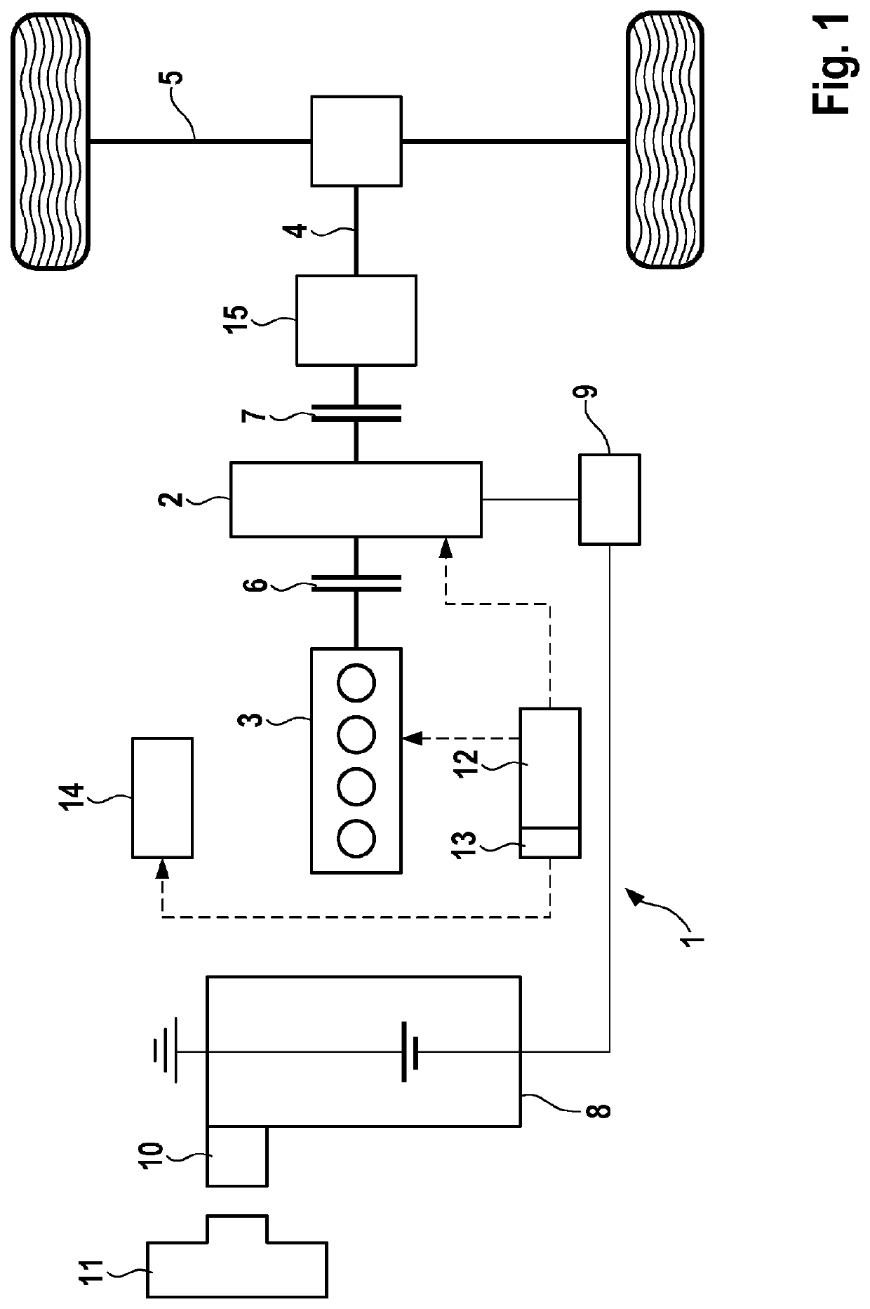
[0047]FIG. 1 shows a block diagram of a hybrid drive system 1 of a motor vehicle, in particular of a plug-in hybrid electric vehicle (PHEV). Drive system 1 has an electric drive 2 and an internal combustion engine 3, which provide required power onto drive axle 5 of drive system 1 via drive shaft 4. Alternatively, it is also conceivable that drive system 1 has multiple electric drives 2 for driving multiple drive axles 5. Furthermore, it is also possible for drive system 1 to be equipped with a four-wheel drive.

[0048]A first clutch 6 for opening and closing the drive train is situated between internal combustion engine 3 and electric drive 2. A first clutch 7 for opening and closing the drive train is situated between internal combustion engine 2 and electric drive 15. Electric drive 2 is supplied by an electrical energy store in the form of a battery 8, which is connected to electric drive 2 via a power electronics 9. The battery 8 may be a traction battery or a high-voltage batter...


PUM


Abstract

A method for operating a hybrid drive system for a motor vehicle having an internal combustion engine and an electrical drive, which is supplied by an electrical energy store, the required powers of the internal combustion engine and / or of the electrical drive being set in accordance with a specified load distribution, including: regulating the load distribution between the electrical drive and the internal combustion engine based on a current setpoint state of charge of the electrical energy store; and determining the current setpoint state of charge from a specified linear setpoint state of charge curve between a current position of the motor vehicle and a destination.

Description

FIELD OF THE INVENTION[0001]The present invention generally relates to a control method for energy management in hybrid drive systems. The present invention in particular relates to operating strategies for operating a vehicle by specifying a load distribution.BACKGROUND INFORMATION[0002]Conventional hybrid vehicles or hybrid electric vehicles (HEV) reclaim kinematic energy in electrical form while driving and store this energy in an electrical energy store such as e.g. a high-voltage (HV) battery, which may be achieved for example by recuperating energy while the vehicle is driving.[0003]PHEV is characterized by the fact that it offers the possibility of charging the electrical energy store through an external power supply network. As a result, a drive system of a PHEV has two types of energy sources available for producing the required vehicle drive energy: namely, conventional fuel based on fossil energy sources for driving the internal combustion engine as well as electrical ene...

Claims


Application Information

Patent Timeline
Patent Type & Authority Patents(United States)
IPC IPC(8): B60W20/13B60W20/12B60K6/48B60W20/00B60K6/20B60W50/00
CPCB60W50/0097B60W20/13B60K6/20B60W20/12Y02T10/84B60W2510/244B60W2710/244B60W2555/40B60K6/48B60Y2200/92B60W2556/50B60W2520/10B60W20/00Y02T10/40Y02T10/62Y02T10/7072Y02T10/70Y02T90/14
Inventor SCHLUMPP, FLORIANRITZERT, JENSRADKE, TOBIAS
Owner ROBERT BOSCH GMBH
Why Eureka
Try Eureka