Temporary pacing lead

a technology of pacing lead and lead electrode, which is applied in the direction of external electrodes, internal electrodes, transvascular endocardial electrodes, etc., can solve the problems of hemodynamic instability of patients, more difficult to place, and more difficult to remove, so as to facilitate and safely reposition, maximize good position, and effective and stable capture

Active Publication Date: 2020-09-15
NEXTERN INNOVATION LLC
View PDF26 Cites 1 Cited by
  • Summary
  • Abstract
  • Description
  • Claims
  • Application Information

AI Technical Summary

Benefits of technology

[0016]The curled shaft of the present invention contains at least one and preferably a plurality of cathode sites all of which are connected together via electrical continuity to form a single cathode or cathode electrode which characterizes the present temporary pacer lead as a unipolar lead. The plurality of cathodes sites allows the present unipolar temporary pacing lead to be easily placed within the chamber of the heart such that at least one of the cathodes sites is in contact with a region of the endocardium to create a capture site that is needed to temporarily pace the heart. The curled shaft applies a small outward force onto two opposing walls of the heart chamber and hence place the cathode sites into contact with the endocardial surface of the myocardium to ensure electrical contact and capture of the pacing signal from the pulse generator.
[0025]Advantages are provided by a loop configuration for the coiled region of the temporary pacing lead including atraumatic contact with the myocardial wall and providing an outward force on the multiplicity of electrodes against the two opposing endocardial walls of the heart chamber to attain consistent capture of the electrical stimulation signal. Most embodiments of the present invention are not required to have a closed loop configuration in order to provide atraumatic contact with the myocardium and maintain effective and stable capture. An open loop distal can have numerous shapes and sizes to maximize good position on multiple sites. Such other embodiments without a closed loop provided by the embodiment with different shapes and sizes give the additional advantage for removal of the pacing lead from the heart chamber without potential for entanglement and potential disruption of cordae tendineae which would create an incompetent TV. The distal region of the curled shaft that forms the curled loop is formed with a low bending modulus material such that the curled loop is easily bent during removal of the pacing lead, still minimizing this risk.

Problems solved by technology

Such arrhythmias can manifest as bradycardia or tachycardia and can result in hemodynamic instability to the patient.
Such active fixation can hold the lead in place but is also more difficult to place during implantation and more difficult to remove after a few days.
Active fixation leads carry a greater likelihood of myocardial perforation and potential for tamponade.
Temporary leads can also have passive fixation such as tines that are designed to be entangled within the trabeculae of the endocardial surface to provide adequate lodging and also can be time-consuming to place.
Other temporary leads are more easily and quickly placed without active or passive fixation elements but still require fluoroscopy and are easily dislodged by small movements of the pacing lead in relation to the patient thereby resulting in loss of capture of the electrical stimulus from the pacemaker generator even due to small micro-dislodgements.
Temporary pacing leads can also have flow-directed balloons located near the distal end to assist with advancement of the pacing lead in the RV chamber but difficult to adequately position for capture and thus require a significant amount of manipulation under fluoroscopy for optimal positioning; flow-directed balloons are less reliable for providing a preferred location for the pacing lead.
Due to the linear configuration, the distal end of the temporary lead can be traumatic to the heart wall and can protrude, penetrate, or perforate through the wall of the heart leading to potential tamponade and which can lead to death of the patient.
Due to the general linear configuration of standard temporary leads, the distal region of the lead does not easily maintain a position adjacent to the endocardial surface which is needed to maintain sustained electrical capture of the myocardial tissue.
Instead the distal region of the lead can easily dislodge and lose capture shortly following placement.
The proximal shaft of such a linearly-configured temporary lead is often secured with sutures and adhesive dressing near its manifold to the patient's tissue near the access site to help prevent dislodgement of the lead and loss of capture, however patient movement and inherent motion of the heart tend to easily result in dislodgement of the lead and resultant loss of capture.
Radiation exposure while using fluoroscopy can be detrimental to a patient.
Several complications exist during the placement and operation of temporary pacemaker leads; such complications include myocardial damage, generation of arrhythmias, perforations of the myocardium, tamponade, trauma to the tricuspid valve, and dislocation or dislodgement of the pacing lead with loss of capture.

Method used


Image

  • Temporary pacing lead
  • Temporary pacing lead
  • Temporary pacing lead

Examples


Embodiment Construction

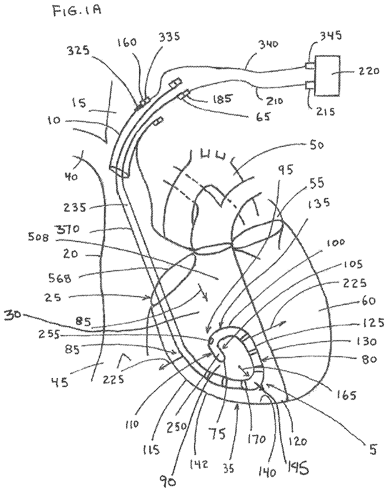
[0079]FIG. 1A shows an embodiment of the present invention for a temporary pacing lead 5. In this embodiment the pacing lead 5 is introduced through an introducer sheath 10 placed in the internal jugular vein (UV) 15; the pacing lead 5 extends through the right atrium (RA) 20 and across the tricuspid valve (TCV) 25 and into the right ventricle (RV) 30 of the heart 35. It is understood, however, that this invention applies also to other entry sites into the vasculature including the subclavian vein (SCV) 40, the femoral vein (FV) 45, the aorta 50, or other blood vessels or conduits of the body; the pacing lead 5 can also be used to pace the RA 20, left atrium (LA) 55, left ventricle (LV) 60 or other chambers of the heart 35 or body.

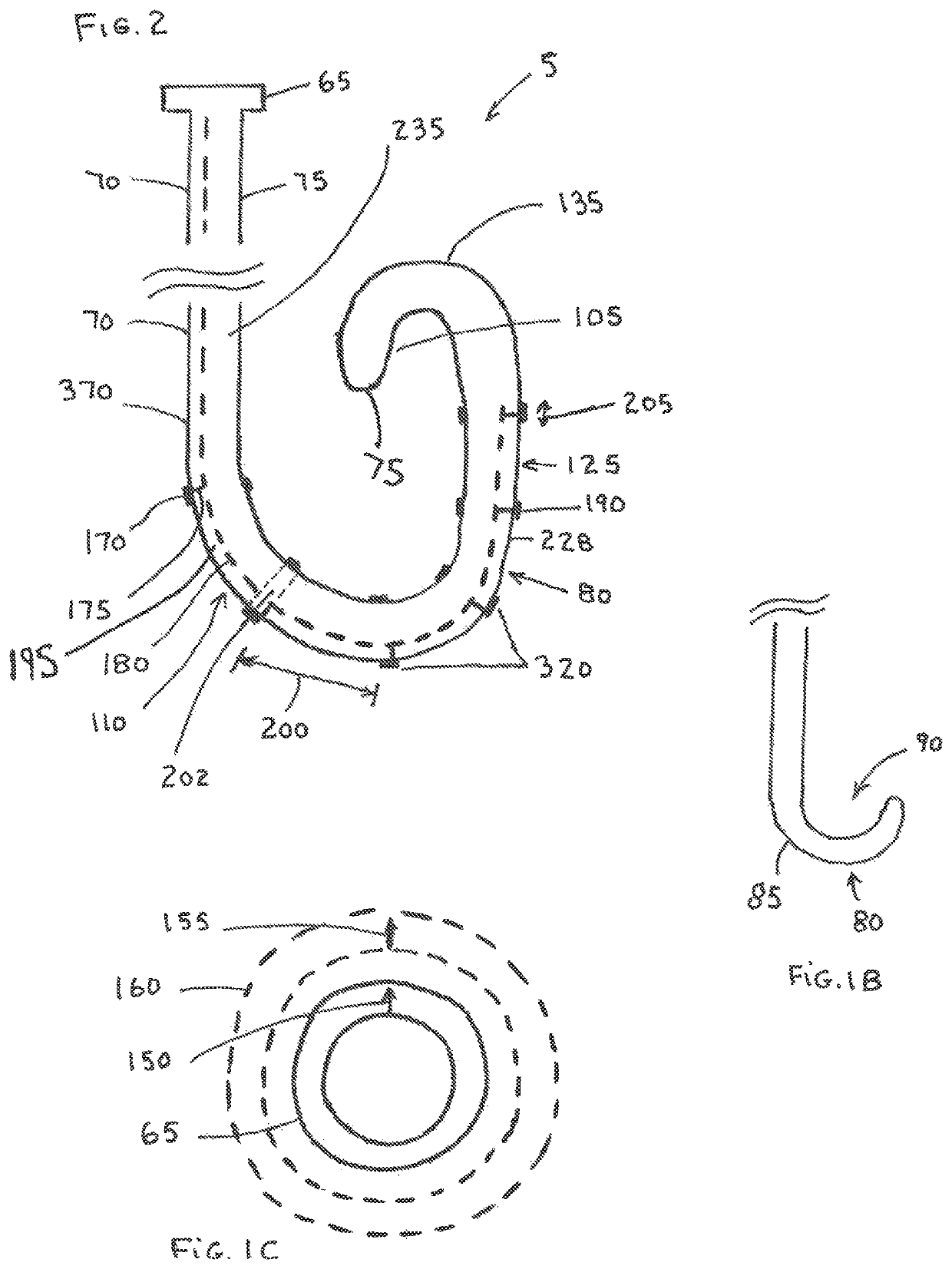
[0080]As shown in FIGS. 1A and 2 the pacing lead 5 has a lead manifold 65 located outside of the body, the lead manifold 65 is attached to the lead body 70 Which extends distally through the introducer sheath 10. The lead body 70 of the pacing lead 5 exten...


PUM


Abstract

A temporary pacing lead has an atraumatic curled distal region with multiple cathodes and distal pressure measurement to allow positioning and repositioning within the heart chamber without fluoroscopic or echo guidance. The curled distal region provides definite contact with two opposing walls of the ventricular chamber to ensure electrical signal capture without trauma to the endocardial surface. A stylet located in the pacing lead lumen assists in introducing, placing, and removing the pacing lead from the heart. The flexible distal region provides safe removal of the temporary lead following completion of use.

Description

CROSS REFERENCE TO RELATED APPLICATIONS[0001]This patent application claims priority to U.S. Provisional Application Ser. No. 62 / 493,490, entitled “Temporary Coiled Pacing Lead,” filed 5 Jul. 2016, U.S. Provisional Application Ser. No. 62 / 495,765 entitled “Temporary Coiled Over the Wire Pacing Lead,” filed 23 Sep. 2016, and U.S. Provisional Application Ser. No. 62 / 602,397 entitled “Temporary Coiled Floppy Distal Pacing Lead,” filed 21 Apr. 2017, all of which are incorporated herein by reference in their entirety.BACKGROUND OF THE INVENTION[0002]Temporary pacing is performed in patients having cardiac arrhythmias as a bridge to permanent pacing or to recovery; temporary pacing also provides prophylactic utility for specific medical procedures including, for example, transcatheter aortic valve replacement (TAVR) procedures. Such arrhythmias can manifest as bradycardia or tachycardia and can result in hemodynamic instability to the patient. Often bradycardia can occur as a result of si...

Claims


Application Information

Patent Timeline
Patent Type & Authority Patents(United States)
IPC IPC(8): A61N1/05
CPCA61N1/056A61N2001/0578
Inventor PEDERSEN, WESLEY ROBERTSORAJJA, PAUL
Owner NEXTERN INNOVATION LLC
Why Eureka
Try Eureka