Photoreceptor for electrophotography, method for manufacturing the same, and electrophotographic device

a photoreceptor and electrophotography technology, applied in the field of photoreceptors, can solve the problems of deterioration of image quality, inability to meet all the properties demanded for photoreceptors for electrophotography, and many advantages of organic materials, and achieves no light fatigue, low residual electric potential, and high sensitivity.

Active Publication Date: 2020-09-22
FUJI ELECTRIC CO LTD
View PDF32 Cites 0 Cited by
  • Summary
  • Abstract
  • Description
  • Claims
  • Application Information

AI Technical Summary

Benefits of technology

[0016]In order to solve the above problems, the present inventors have intensively studied to find that, by using a polyarylate resin for the outermost surface layer of a photoreceptor and adding a specific electron transport material, a photoreceptor with high sensitivity, low residual potential, no light fatigue, penetration of a component which leaks from a constituent member of a charging roller or a transfer roller into the surface of a photoreceptor suppressed, and stain resistance improved can be obtained, thereby completing the present invention.
[0027]The present invention can realize a photoreceptor for electrophotography with high sensitivity, low residual electric potential, no light fatigue, suppressed penetration of a component which leaks from a constituent member of a charging roller or a transfer roller into the surface of a photoreceptor, and improved stain resistance.

Problems solved by technology

Organic materials have many advantages not found in inorganic materials, but have not been able to satisfy all the properties demanded for photoreceptors for electrophotography.
In other words, deterioration of image quality is caused by a decrease in charged electric potential due to repeated use, an increase in residual potential, a change in sensitivity, or the like.
The cause of this deterioration is not completely understood, but as a factor, it is conceivable that a resin is photo-deteriorated, an electric charge transport material is decomposed, or the like by repetitive exposure to image exposure light and charge removing lamp light or exposure to external light during maintenance.
Since a photoreceptor always contacts a charging roller or a transfer roller, the surface of the photoreceptor is contaminated by components of members constituting such rollers, and black streaks are generated in a halftone image, which is problematic.
However, these methods failed to sufficiently respond to the stain resistance.
Regarding the stain resistance, a polyarylate resin exhibits favorable stain resistance results as compared with a polycarbonate resin in the outermost surface layer of a photoreceptor, but on the other hand, there is concern that degradation by light may occur.
Specifically, the polyarylate resin has a high ultraviolet absorbing ability, absorbs ultraviolet energy, causes a Fries rearrangement reaction, and forms a benzophenone structure in a resin surface layer portion, and therefore, the resin is weak against light resistance.
However, sufficient effects have not been obtained even by the above-described conventional techniques.
Further, in a technique of adding a dye or an ultraviolet absorber as described above, there has also been a problem that sensitivity reduction, residual electric potential increase, and the like are caused.

Method used


Image

  • Photoreceptor for electrophotography, method for manufacturing the same, and electrophotographic device
  • Photoreceptor for electrophotography, method for manufacturing the same, and electrophotographic device
  • Photoreceptor for electrophotography, method for manufacturing the same, and electrophotographic device

Examples


example 1

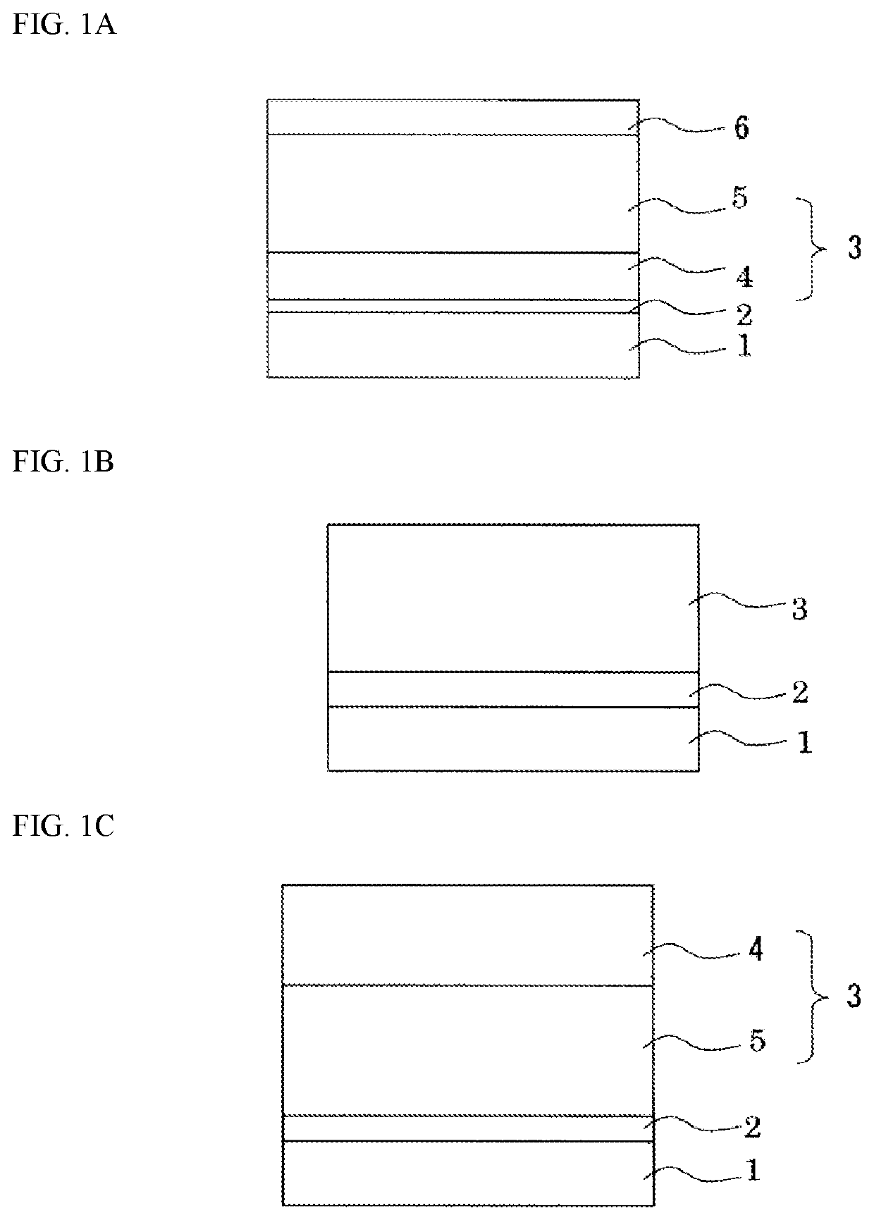
[0112]Five parts by mass of alcohol-soluble nylon (trade name “CM8000” manufactured by Toray Industries, Inc.) and 5 parts by mass of aminosilane-treated titanium oxide fine particles were dissolved and dispersed in 90 parts by mass of methanol to prepare a coating liquid 1. This coating liquid 1 was dip coated on the outer circumference of an aluminum cylinder having an outer diameter of 30 mm as the conductive substrate 1, and dried at a temperature of 100° C. for 30 minutes to form an undercoat layer 2 having a thickness of 3 μm.

[0113]One part by mass of Y-type titanyl phthalocyanine as an electric charge generating material and 1.5 parts by mass of polyvinyl butyral resin (trade name “5-LEC KS-1” manufactured by Sekisui Chemical Co., Ltd.) as a resin binder were dissolved and dispersed in 60 parts by mass of dichloromethane to prepare a coating liquid 2. This coating liquid 2 was dip coated on the undercoat layer 2 and dried at a temperature of 80° C. for 30 minutes to form a ch...
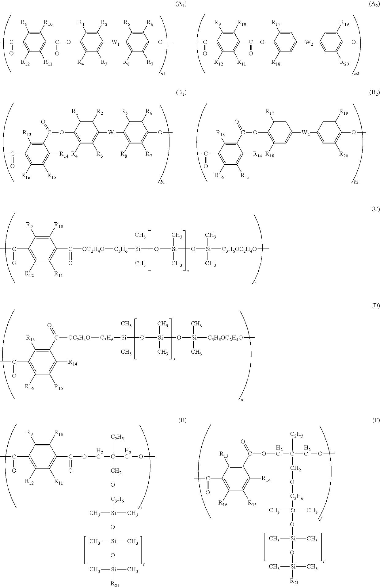
examples 2 to 32

[0116]Photoreceptors were prepared in the same manner as in Example 1 except that the polyarylate resin represented by the structural formula (I-1) used in Example 1 was replaced with polyarylate resins represented by structural formulae (I-2) to (I-32), respectively. The prepared photoreceptor was left to stand for 30 days in the same manner as in Example 1.

example 33

[0117]A photoreceptor was prepared in the same manner as in Example 1 except that the Y-type titanyl phthalocyanine used in Example 1 was replaced with α-type titanyl phthalocyanine. The prepared photoreceptor was left to stand for 30 days in the same manner as in Example 1.


PUM

PropertyMeasurementUnit
thicknessaaaaaaaaaa
thicknessaaaaaaaaaa
thicknessaaaaaaaaaa

Abstract

A photoreceptor for electrophotography, a method for manufacturing the photoreceptor, and an electrophotographic device including the photoreceptor are disclosed. The photoreceptor for electrophotography includes a conductive substrate; and a photosensitive layer that is provided on the conductive substrate and that has an outermost surface layer containing at least a resin binder and an electron transport material. The resin binder is composed of a polyarylate resin having a structural unit represented by a Chemical Structural Formula 1, and the electron transport material is composed of a compound having a structure represented by a Structural Formula (ET2-3). The photoreceptor has high sensitivity, low residual electric potential, no light fatigue and sufficient stain resistance.

Description

CROSS-REFERENCE TO RELATED APPLICATIONS[0001]This application is a continuation of PCT Application No. PCT / JP2015 / 080836 filed Oct. 30, 2015, the entire contents of which are incorporated herein by reference.BACKGROUND OF THE INVENTION1. Field of the Invention[0002]The present invention relates to a photoreceptor for electrophotography (hereinafter, also simply referred to as “photoreceptor”) used for electrophotographic printers, copying machines, fax machines, and the like, a method for manufacturing the same, and an electrophotographic device, and in particular, to a photoreceptor for electrophotography having high sensitivity, low residual electric potential, no light fatigue, and favorable stain resistance by combining a polyarylate resin and a specific electron transport material, a method for manufacturing the same, and an electrophotographic device.2. Background of the Related Art[0003]Photoreceptors for electrophotography demand a function to retain surface charge in a dark...

Claims


Application Information

Patent Timeline
Patent Type & Authority Patents(United States)
IPC IPC(8): G03G5/05G03G15/00G03G5/06G03G5/047G03G5/147
CPCG03G5/0609G03G5/0603G03G5/056G03G5/0677G03G5/0589G03G5/047G03G5/0631G03G5/0612G03G5/0605G03G15/75G03G15/751G03G5/0525G03G5/0578G03G5/147
Inventor ZHU, FENGQIANGSUZUKI, SHINJIROTAKEUCHI, TOSHIKI
Owner FUJI ELECTRIC CO LTD
Why Eureka
Try Eureka