Percutaneous implantable nuclear prosthesis

a nuclear prosthesis and implantable technology, applied in the field of percutaneous implanted spinal discs, to achieve the effects of reducing stress, reducing stress, and long working li

a nuclear prosthesis and implantable technology, applied in the field of percutaneous implanted spinal discs, to achieve the effects of reducing stress, reducing stress, and long working li

US10786360B2Active Publication Date: 2020-09-29SPINAL STABILIZATION TECH

Image

  • Percutaneous implantable nuclear prosthesis
  • Percutaneous implantable nuclear prosthesis
  • Percutaneous implantable nuclear prosthesis

Examples


Embodiment Construction

[0065]In the following detailed description, reference is made to the accompanying drawings, in which are shown exemplary but non-limiting and non-exhaustive embodiments of the invention. These embodiments are described in sufficient detail to enable those having skill in the art to practice the invention, and it is understood that other embodiments may be used, and other changes may be made, without departing from the spirit or scope of the invention. The following detailed description is, therefore, not to be taken in a limiting sense, and the scope of the invention is defined only by the appended claims. In the accompanying drawings, like reference numerals refer to like parts throughout the various figures unless otherwise specified.

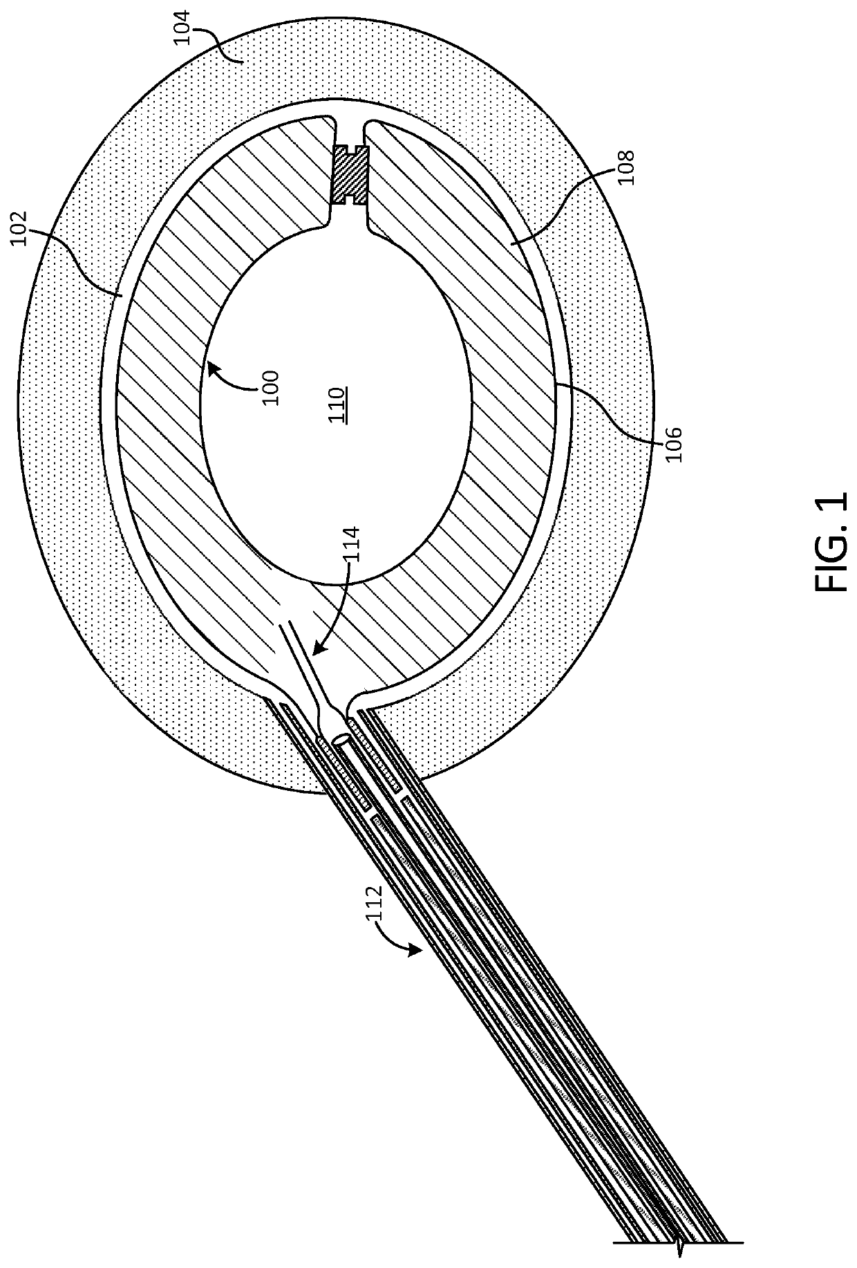
[0066]FIG. 1 illustrates an implant 100 in accordance with an exemplary embodiment of the present disclosure after deployment into a disc cavity 102. The disc cavity 102 is formed by performing a discectomy to remove the natural spinal disc. In some ...


PUM

PropertyMeasurementUnit
inner diameteraaaaaaaaaa
outer diameteraaaaaaaaaa
hardnessesaaaaaaaaaa

Abstract

A prosthesis for implantation in a de-nucleated intervertebral disc includes a fiber ring-like layer which encloses a polymeric layer to create an annular space. The annular space is inflatable with an in-situ curable liquid polymer and forms an interior cavity. The annular space may be expanded uniformly or differentially to be tailored to the needs of a particular vertebral segment and to achieve optimal disc space width and angle, thereby stabilizing the segment while preserving normal motion of the vertebral segment. The interior cavity provides a void that allows inward deformation of the implant during weight bearing activities and bending. The prosthesis can be elastically deformed through axial elongation to a reduced profile to load into a delivery cannula using pulling techniques.

Description

CROSS-REFERENCE TO RELATED APPLICATIONS[0001]This application claims the benefit of priority of U.S. Provisional Patent Application No. 62 / 074,873, filed Nov. 4, 2014, which is hereby incorporated by reference in its entirety.BACKGROUND[0002]1. Field of the Invention[0003]This application relates generally to methods and devices for repairing an intervertebral disc. More specifically, the application relates to percutaneously deployed implantable spinal discs and methods for manufacturing and deploying such discs.[0004]2. Description of Related Art[0005]A common medical issue is back pain due to spinal disc injuries caused by trauma, the aging process or other disorders. One method of treatment that has been proposed is to remove the existing nucleus pulposus and replace it with a nuclear prosthesis (i.e., an artificial spinal disk) which is formed in situ using open surgery or minimally invasive surgical techniques.[0006]Prior artificial disc technology has generally employed two t...

Claims


Application Information

Patent Timeline
29 Sep 2020
Publication
US10786360B2
IPC
A61F2/44; A61F2/30; A61F2/46
CPC
A61F2/4611; A61F2/442; A61F2/441; A61F2002/30583; A61F2002/30581; A61F2002/4495; A61F2002/30586; A61F2002/444
Inventors
HIBRI, NADI S.; FRANCIS, W. LOREN