
Active energy ray-curable resin composition, antifogging antifouling laminate, article, method for producing same, and antifouling method

a technology of active energy raycurable resin, which is applied in the direction of synthetic resin layered products, antifouling/underwater paints, and layered product treatment, etc. it can solve the problems of low producibility of proposed techniques and reduce visibility and good appearance of products, and achieve excellent anti-fogging properties, anti-fouling properties and producibility effects

Active Publication Date: 2020-12-29
DEXERIALS CORP
View PDF30 Cites 0 Cited by
  • Summary
  • Abstract
  • Description
  • Claims
  • Application Information

AI Technical Summary

Benefits of technology

The present invention provides an anti-fogging and anti-fouling laminate that overcomes the problems of the prior art. The laminate has excellent anti-fogging and anti-fouling properties, is easy to produce, and can be used in various products. The invention also provides a method for manufacturing the laminate and an anti-fouling method using it. Additionally, the invention includes an active energy ray curable resin composition that can be used for manufacturing the laminate.

Problems solved by technology

However, the resin films and glass decorating and protecting the surfaces of products sometimes get cloudy and dirty to reduce visibility and good appearance of the products.
However, this proposed technique shows low producibility because the three layers (i.e., the underlying layer, the water absorption layer and the protective layer) are laminated on the surface of the substrate, which is problematic.

Method used


Image

  • Active energy ray-curable resin composition, antifogging antifouling laminate, article, method for producing same, and antifouling method
  • Active energy ray-curable resin composition, antifogging antifouling laminate, article, method for producing same, and antifouling method
  • Active energy ray-curable resin composition, antifogging antifouling laminate, article, method for producing same, and antifouling method

Examples


example 1

Preparation of Anti-Fogging and Anti-Fouling Laminate

[0230]As the substrate made of a resin, FE-2000 (PC substrate, average thickness of 180 μm, manufactured by MITSUBISHI GAS CHEMICAL COMPANY, INC.) was used.

[0231]Next, an active energy ray curable resin composition having the following formulation was coated on the substrate made of a resin so that a thickness of the coating was 4 μm. A metal halide lamp was used to emit an ultraviolet ray at a radiation dose of 1,800 mJ / cm2 under nitrogen atmosphere and cure the resultant anti-fogging and anti-fouling layer to obtain an anti-fogging and anti-fouling laminate.

[0232]

-Active energy ray curable resin composition(total: 100% by mass)-NK ESTER A-GLY-20E (manufactured by Shin67.307%by massNakamura Chemical Co., Ltd.)PETIA (manufactured by DAICEL-ALLNEX LTD.)28.846%by massKY1203 (manufactured by Shin-Etsu Chemical0.962%by massCo., Ltd.)IRGACURE 184D (manufactured by BASF)2.885%by mass

[0233]The anti-fogging and anti-fouling laminate obtai...

example 9

[0270]An anti-fogging and anti-fouling laminate was obtained in the same manner as in Example 5 except that the thickness of the coating was changed to 10 μm.

[0271]The anti-fogging and anti-fouling laminate obtained was evaluated in the same manner as in Example 5. Moreover, the interference irregularity was evaluated. Results are presented in Table 2. The interference irregularity of Example 5 presented an evaluation result of B, while that of Example 9 presented an evaluation result of A.

[0272]The anti-fogging and anti-fouling laminate and the black acrylic board (manufactured by MITSUBISHI RAYON CO., LTD., product name: ACRYLITE) were attached together using a piece of double-coated adhesive tape (manufactured by NISSHO CORPORATION, product name: LUCIACS CS9621T) so that a surface to be evaluated (i.e., a surface of the anti-fogging and anti-fouling laminate) faced upward. Then, the surface to be evaluated was observed under a white fluorescent lamp and was evaluated based on the...

example 10

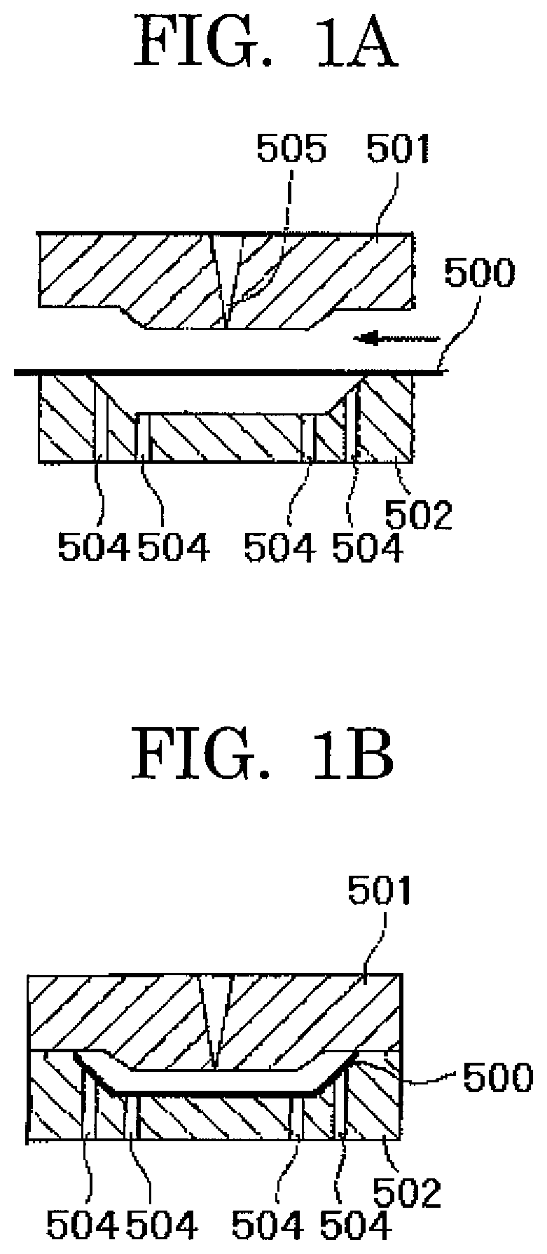
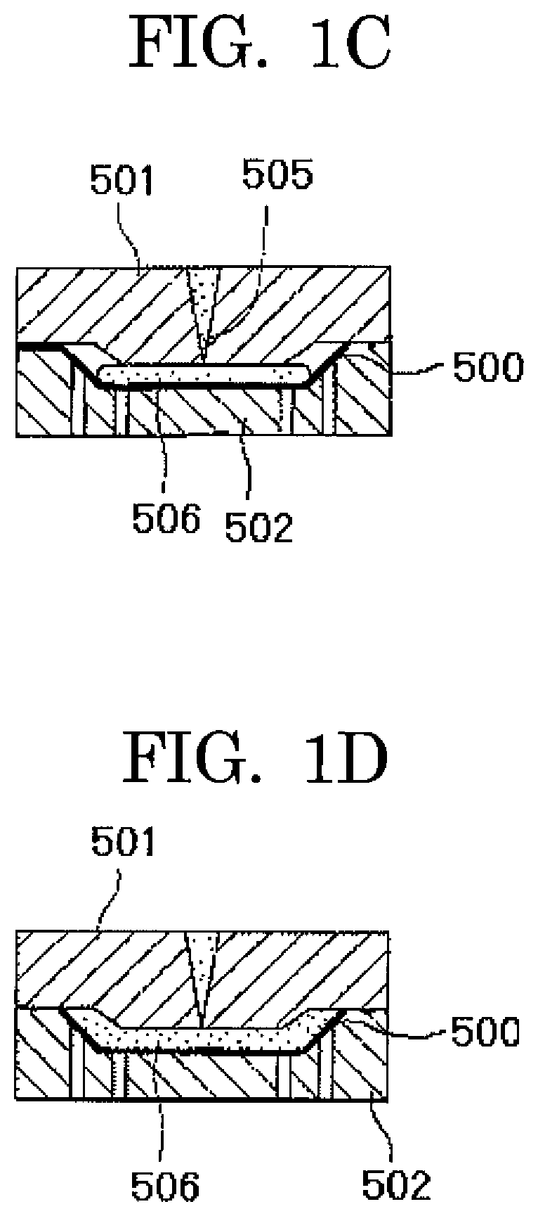
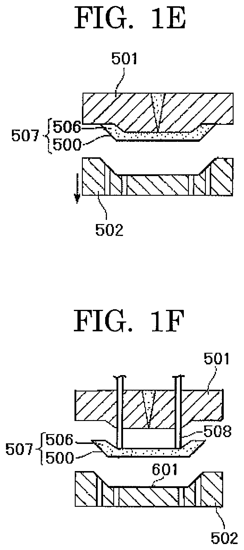
[0274]The anti-fogging and anti-fouling laminate prepared in Example 9 was exposed to the atmosphere of 400° C. for 13 seconds and was molded into an 8 curve lens (diameter: 80 mm) so that a concave surface was the anti-fogging and anti-fouling layer through vacuum molding. The anti-fogging and anti-fouling layer did not have any poor appearance such as scratch, crack and peering. Then, the anti-fogging and anti-fouling laminate having an 8 curve lens (diameter: 80 mm) was subjected to punching with a Tomson blade. The mater that had undergone the punching was set to a mold for insert molding and the melted polycarbonate was loaded into the mold. The mold was cooled until polycarbonate was solidified. Then, the molds were separated to obtain an 8 curve lens where a concave surface of the lens was an anti-fogging and anti-fouling layer. The 8 curve lens obtained was directly applied to hard coat layer-forming steps (step of washing lens, step of immersing the lens in a hard coat solu...


PUM

PropertyMeasurementUnit
contact angleaaaaaaaaaa
water contact angleaaaaaaaaaa
thicknessaaaaaaaaaa

Abstract

An anti-fogging and anti-fouling laminate, including: a substrate; and an anti-fogging and anti-fouling layer on the substrate where a surface of the anti-fogging and anti-fouling layer is flat, wherein the anti-fogging and anti-fouling layer is a cured product obtained by curing an active energy ray curable resin composition through an active energy ray, wherein the active energy ray curable resin composition includes a hydrophilic monomer having a radically polymerizable unsaturated group and a photopolymerization initiator, wherein a content of the hydrophilic monomer having a radically polymerizable unsaturated group in the active energy ray curable resin composition is 60% by mass or more, and wherein a surface of the anti-fogging and anti-fouling layer has a pure water contact angle of 90° or more.

Description

TECHNICAL FIELD[0001]The present invention relates to an anti-fogging and anti-fouling laminate, a product using the anti-fogging and anti-fouling laminate, a method for manufacturing the product, an anti-fouling method using the anti-fogging and anti-fouling laminate, and an active energy ray curable resin composition that can be used for manufacturing the anti-fogging and anti-fouling laminate. The anti-fogging and anti-fouling laminate has anti-fogging and anti-fouling properties, and can be used in a wide variety of fields (building use, industrial use, automobile use, optical use, solar battery panels, etc.). In addition, the anti-fogging and anti-fouling laminate can be manufactured through a simple molding process.BACKGROUND ART[0002]To decorate and protect the surfaces of products, resin films and glass and the like are attached to the surfaces.[0003]However, the resin films and glass decorating and protecting the surfaces of products sometimes get cloudy and dirty to reduce...

Claims


Application Information

Patent Timeline
Patent Type & Authority Patents(United States)
IPC IPC(8): C08J7/04B32B38/18B32B15/095B32B15/088B32B15/085C08F220/28C08F290/06B29C45/14B29C45/72C08F222/10B32B27/34C09D5/16B32B9/00B32B15/082B32B15/09B32B9/04B32B27/32B32B27/28B32B23/08B32B23/20B32B27/38B32B27/08B32B27/30B32B7/12B32B27/36B32B27/42C08F20/20C08F2/48C09D4/00C09D135/02B32B27/00B32B27/16B32B27/40B32B7/02B32B15/18B32B15/20C08F20/24C09D151/08C08J7/043C08J7/046C08J7/054C08J7/056
CPCC08F20/20B32B27/00B32B27/38B32B15/18B32B27/16B32B9/002C09D5/1668C09D135/02B32B27/308C08J7/0427B32B27/302B32B27/08B32B27/36B32B27/365C08F220/28B32B15/082B32B27/42B32B23/08C08F2/48B32B23/20B32B27/304B32B15/20B32B15/088B32B15/095B32B15/085B32B27/325B32B27/32C08F222/1006B32B7/12B32B27/285B32B27/30C08F290/062C09D4/00B29C45/14B32B38/1866B32B27/34B32B7/02B32B27/281B32B9/045B32B15/09B32B27/286B32B27/40B29C45/72C08F222/104C08F220/24B32B2250/03C08F220/286C08F20/24B32B2255/28B32B2307/40C08F222/103C08J2369/00B32B2605/006B32B2307/73B32B2255/10B32B2255/26C09D151/08B32B2307/50B32B2307/756B32B2255/06C08J2435/02B32B2250/40B32B2250/24B32B2307/418B32B2250/02B29C2045/14155B32B2551/08B32B2307/412B32B2457/12C08J7/043C08J7/054C08J7/046C08J7/056B32B37/06C08F20/26C08J7/04C09D5/1681B32B2310/0825B32B27/18B32B2305/72
Inventor SAKAMOTO, SHOGOENDO, RYOSUKEMIZUNO, MIKIHISAHARA, SHINOBU
Owner DEXERIALS CORP
Learn More