Reformer-electrolyzer-purifier (REP) assembly for hydrogen production, systems incorporating same and method of producing hydrogen

a purifier and electrochemical technology, applied in the direction of electrochemical generators, fuel cells of fused electrolyte, energy input, etc., can solve the problems of high process efficiency, reduced efficiency and cosub>2 production, and conventional hydrogen production from natural gas and other fuels suffers. , to achieve the effect of low cost and low greenhouse emissions

Active Publication Date: 2021-01-12
FUELCELL ENERGY INC
View PDF128 Cites 0 Cited by
  • Summary
  • Abstract
  • Description
  • Claims
  • Application Information

AI Technical Summary

Benefits of technology

[0006]The objective of the present invention is to provide a low cost system for producing hydrogen with low greenhouse emissions.
[0007]The present invention reforms and purifies hydrogen from natural gas and other fuels in one step. Electricity used to electrochemically purify the hydrogen at high temperature produces additional hydrogen from steam electrolysis at the same time. Moreover, waste heat is utilized to drive the endothermic reforming reaction, eliminating emissions which would otherwise be produced by burning fuel. The system of the present invention incorporates a high temperature electrochemical purification system to remove CO2 from the reformed gas during the reforming process and to drive the conversion of methane to H2 and CO2 to completion, producing hydrogen from fuel in a manner which approaches the theoretical minimum of CO2 emissions.
[0008]The single step system of the present invention simplifies operations and results in a low cost system. In addition, the system of the present invention can generate hydrogen for both central and distributed production and has other possible uses, such as enabling CO2 capture and energy storage.
[0009]Moreover, the present invention generates hydrogen from reforming fuel, such as natural gas, and high temperature electrolysis, lowering the marginal production cost of hydrogen. As a result, the total cost of hydrogen is economically attractive.

Problems solved by technology

This process is highly inefficient due to the high power consumption required by low temperature electrolysis.
Conventional technologies for production of hydrogen from natural gas and other fuels also suffer from lower efficiency and excess CO2 production due to incomplete conversion of methane and CO to hydrogen and from other disadvantages.
For example, conventional hydrogen production and separation systems which use a steam methane reformer (SMR) coupled to a pressure swing adsorption (PSA) device suffer from the disadvantage of not converting all of the methane to hydrogen, and thus a substantial amount of feed energy is converted to heat.
This generation of heat makes it impractical for the system to use waste heat from other sources to improve efficiency and also increases CO2 emissions.
These conventional systems also suffer from efficiency losses and cost increases when scaled down from today's typical 500,000 kilograms per day systems and typically produce a significant amount of NOx in addition to the high CO2 emissions.
This can make obtaining permission to install and operate these conventional systems difficult, particularly in nonindustrial areas.
For renewable feeds, such systems operate even less efficiently due to the dilution of the feed with CO2 and required compression of the feed stream.

Method used


Image

  • Reformer-electrolyzer-purifier (REP) assembly for hydrogen production, systems incorporating same and method of producing hydrogen
  • Reformer-electrolyzer-purifier (REP) assembly for hydrogen production, systems incorporating same and method of producing hydrogen
  • Reformer-electrolyzer-purifier (REP) assembly for hydrogen production, systems incorporating same and method of producing hydrogen

Examples


Embodiment Construction

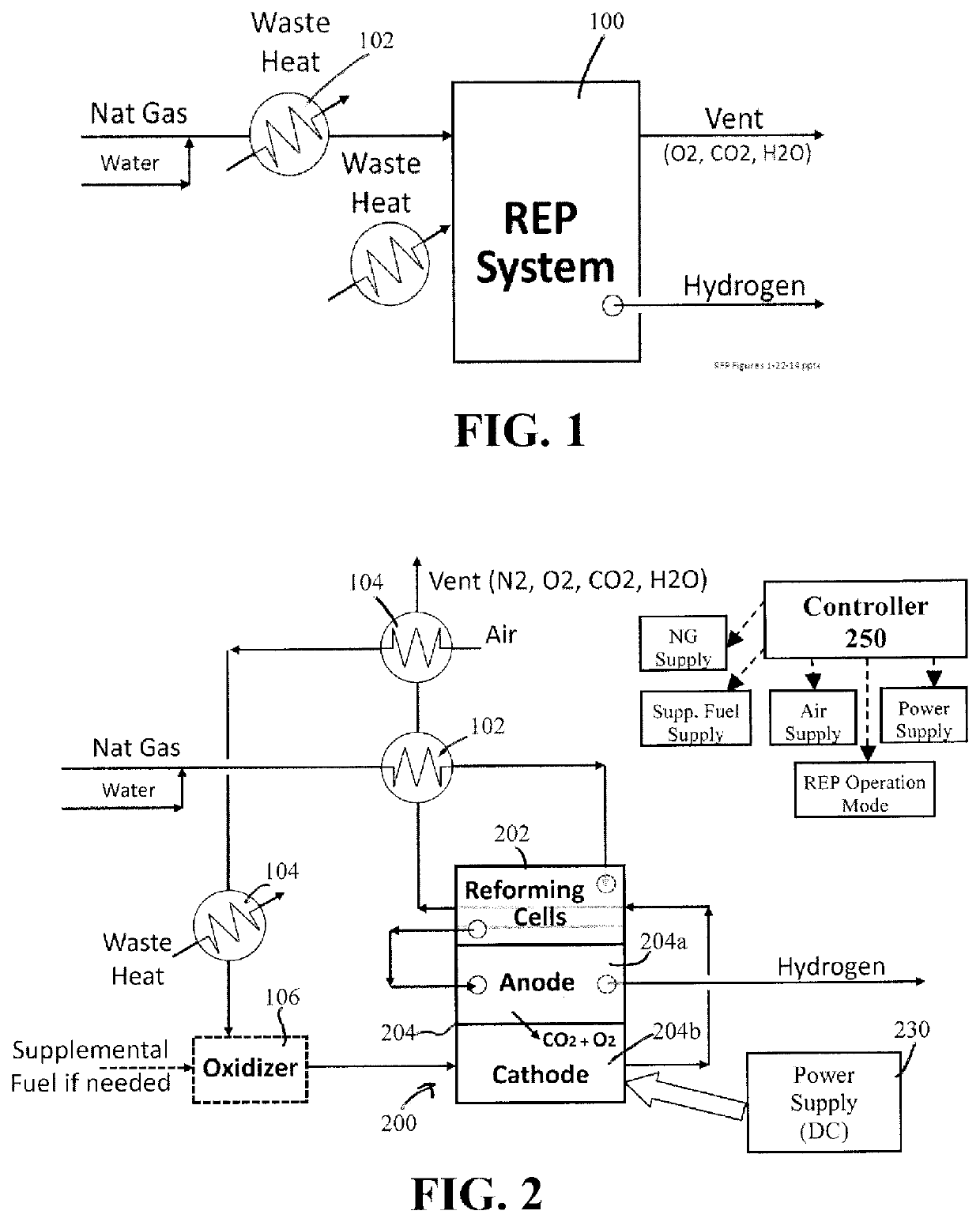
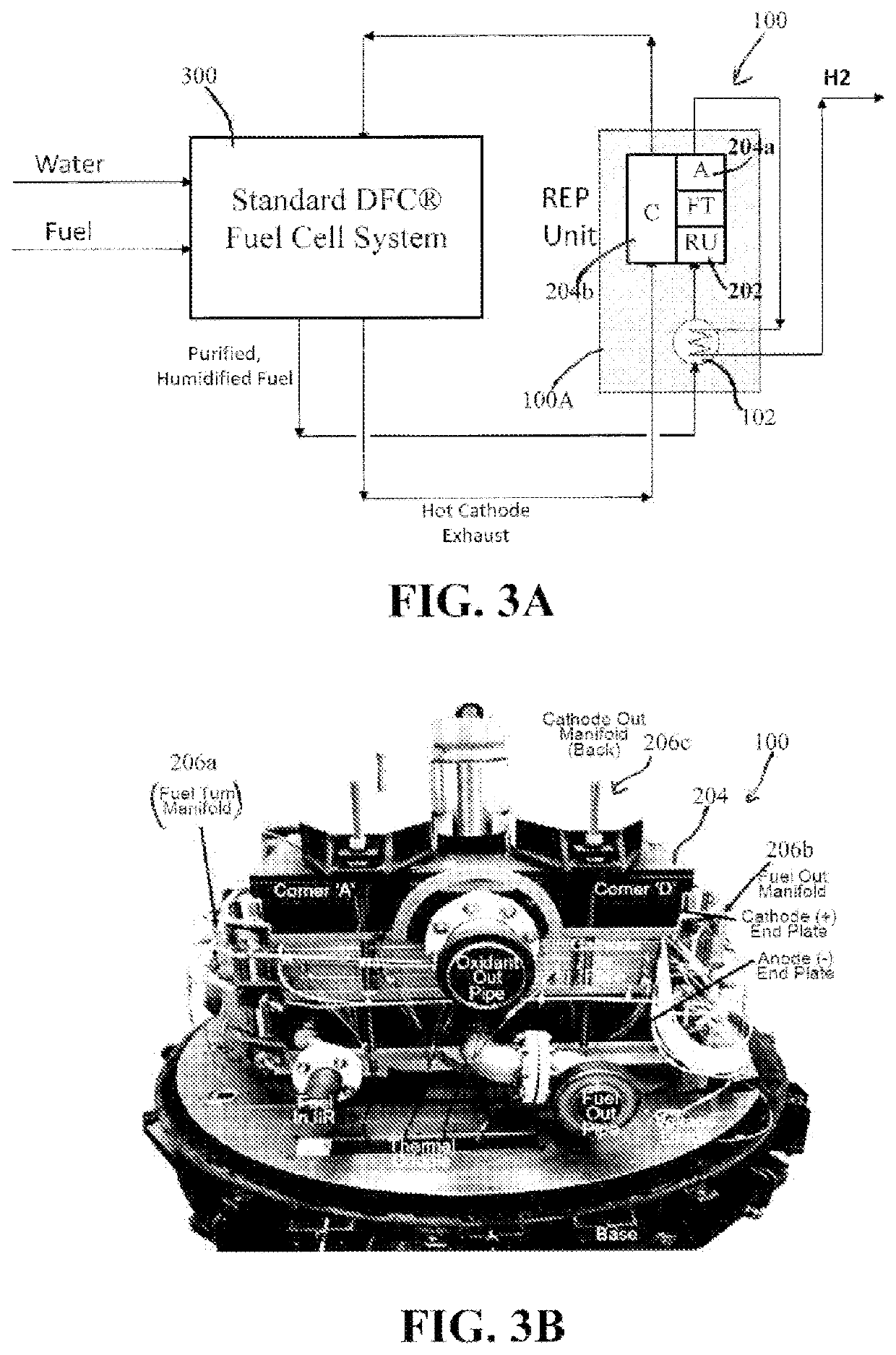
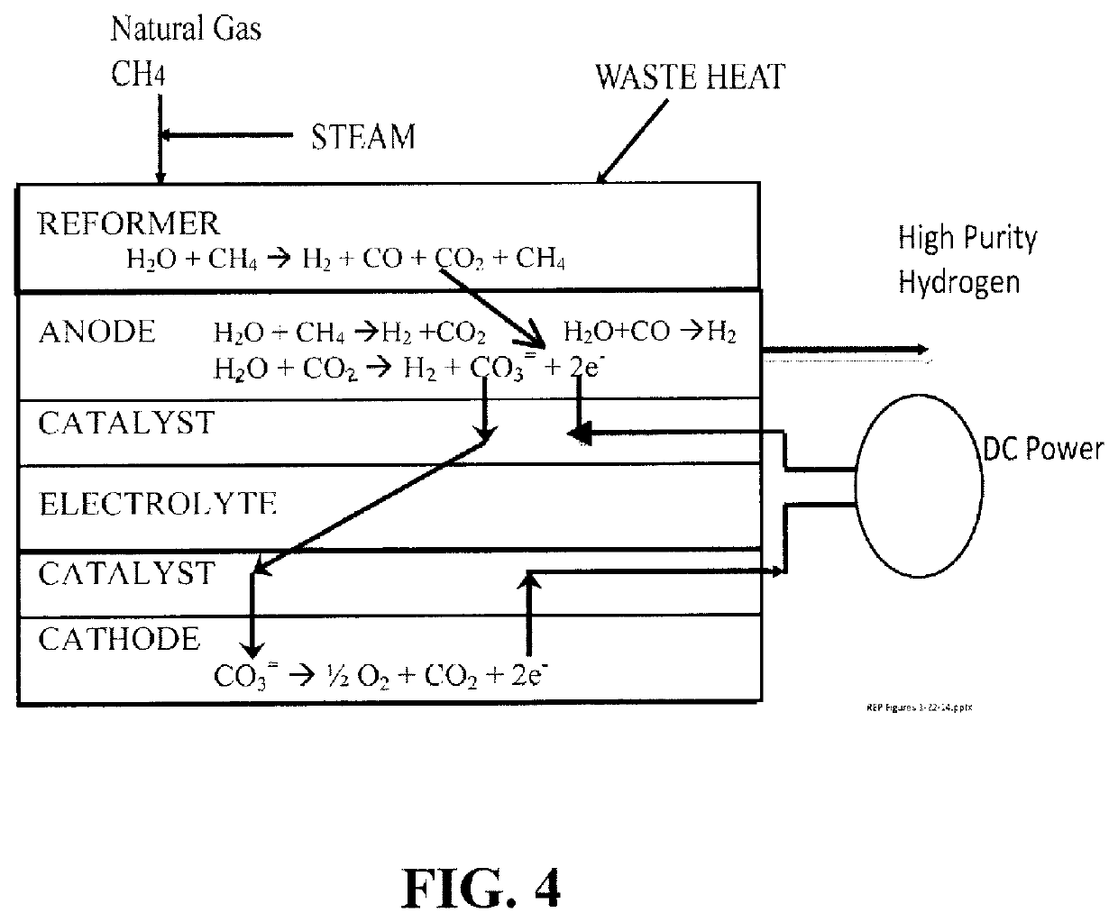
[0027]The present invention is directed to a high temperature electrolyzer assembly, also referred to throughout the specification as a reformer-electrolyzer-purifier (REP) assembly, and various systems including the REP assembly. As described below, the REP assembly includes at least one electrolyzer fuel cell and may include a plurality of electrolyzer fuel cells formed in a fuel cell stack, also referred to as a REP stack. The at least one electrolyzer fuel cell is operated in reverse so as to electrolyze CO2 and water to produce hydrogen, and to purify the hydrogen by removing the CO3=. The CO2 may be provided by a hydrocarbon, such as methane, and removing the CO3= drives the reforming reaction to completion. Other reactions may occur in the at least one electrolyzer fuel cell, as described below and shown in the accompanying Figures.

[0028]The REP stack preferably comprises a molten carbonate fuel cell stack and the REP assembly includes a power supply for supplying power to th...


PUM

PropertyMeasurementUnit
reverse voltageaaaaaaaaaa

Abstract

A high temperature electrolyzer assembly comprising at least one electrolyzer fuel cell including an anode and a cathode separated by an electrolyte matrix, and a power supply for applying a reverse voltage to the at least one electrolyzer fuel cell, wherein a gas feed comprising steam and one or more of CO2 and hydrocarbon fuel is fed to the anode of the at least one electrolyzer fuel cell, and wherein, when the power supply applies the reverse voltage to the at least one electrolyzer fuel cell, hydrogen-containing gas is generated by an electrolysis reaction in the anode of the at least one electrolyzer fuel cell and carbon dioxide is separated from the hydrogen-containing gas so that the at least one electrolyzer fuel cell outputs the hydrogen-containing gas and separately outputs an oxidant gas comprising carbon dioxide and oxygen.

Description

Cross Reference to Related Applications[0001]This application is a U.S. National Stage Application under 35 U.S.C. § 120 of PCT / US2015 / 013837, filed Jan. 30, 2015, which claims the benefit of U.S. Provisional Application 61 / 934,466, filed Jan. 31, 2014, which are both incorporated herein by reference in their entirety.STATEMENT OF GOVERNMENT RIGHTS[0002]The Government has rights in this invention pursuant to Contract No. DE-EE0006669 awarded by the U.S. Department of Energy.BACKGROUND OF THE INVENTION[0003]This invention relates to production of hydrogen from fuel, such as natural gas, methane, ADG digester gas and others, and in particular, to using a fuel reformer-electrolyzer-purifier assembly for hydrogen production and capable of being integrated with a fuel cell system and other systems. This invention further relates to various applications of the fuel reformer-electrolyzer-purifier assembly and systems incorporating the same.[0004]Hydrocarbon fuels, such as methane, propane,...

Claims


Application Information

Patent Timeline
Patent Type & Authority Patents(United States)
IPC IPC(8): H01M8/0612H01M8/18H01M8/12H01M8/14H01M8/0668C25B15/08C25B1/04H01M8/04089H01M8/1018H01M8/124
CPCH01M8/0618C25B1/04C25B15/08H01M8/04089H01M8/0668H01M8/12H01M8/145H01M8/186H01M2008/1095H01M2008/1293H01M2008/147Y02E60/366Y02E60/526Y02E60/528Y02P20/129Y02E60/50Y02E60/36H01M8/0656
Inventor JAHNKE, FRED C.LAMBRECH, MATTHEWPATEL, PINAKINFAROOQUE, MOHAMMADYUH, CHAO-YI
Owner FUELCELL ENERGY INC
Why Eureka
Try Eureka